


CARBON MONOXIDE POISONING HAZARD
Failure to follow the steps outlined below for each appliance connected to the venting system being placed
into operation could result in carbon monoxide poisoning or death.
The following steps shall be followed for each appliance connected to the venting system being placed into
operation, while all other appliances connected to the venting system are not in operation:
1. Seal any unused openings in the venting system.
2. Inspect the venting system for proper size and horizontal pitch, as required in the National Fuel Gas Code,
ANSI Z223.1/NFPA 54 or the CSA B149.1, Natural Gas and Propane Installation Codes and these
instructions. Determine that there is no blockage or restriction, leakage, corrosion and other deficiencies
which could cause an unsafe condition.
3. As far as practical, close all building doors and windows and all doors between the space in which the
appliance(s) connected to the venting system are located and other spaces of the building.
4. Close fireplace dampers.
5. Turn on clothes dryers and any appliance not connected to the venting system. Turn on any exhaust fans,
such as range hoods and bathroom exhausts, so they are operating at maximum speed. Do not operate
a summer exhaust fan.
6. Follow the lighting instructions. Place the appliance being inspected into operation. Adjust the thermostat
so appliance is operating continuously.
7. Test for spillage from draft hood equipped appliances at the draft hood relief opening after 5 minutes of main
burner operation. Use the flame of a match or candle.
8. If improper venting is observed during any of the above tests, the venting system must be corrected in
accordance with the National Fuel Gas Code, ANSI Z223.1/NFPA 54 and/or CSA B149.1, Natural Gas and
Propane Installation Codes.
9. After it has been determined that each appliance connected to the venting system properly vents when
tested as outlined above, return doors, windows, exhaust fans, fireplace dampers and any other gas-fired
burning appliance to their previous conditions of use.
ELECTRICAL CONNECTIONS
When installed, the furnace must be electrically
grounded in accordance with local codes or, in the
absence of local codes, with the (U.S.) National Electrical
Codes, ANSI/NFPA 70 or CSA Standard C22.1; Part 1
Canadian Electrical Code. For proper installation refer to
furnace rating label for electrical ratings and for the field
wiring of this unit refer to furnace wiring specifications on
page 5 or alternately from the wiring diagram on page 27.
In all instances, other than wiring for the thermostat, the
wiring to be done and any replacement of wire shall
conform with the temperature limitation for Type T wire
[63°F rise (35°C)].
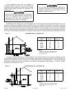
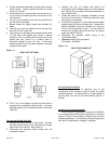
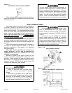
The electrical connections and the thermostat
connections are made at the openings on either side
panel of the unit in the control box area. Either side may
be used as convenient, but the provided hole plugs must
be inserted in the unused holes.
The control system depends on the correct polarity of
the power supply. Connect "Hot" (H) wire and "Ground"
(G) wire as shown in furnace wiring specification on
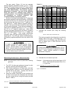
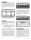
wiring diagram. Use reference Table on page 3 (Furnace
Specifications), for over current protection, max unit amp
rating and wire size. Use copper wire only for 115V-
supply service to unit. When replacing any original
internal wiring, use only 105°C, 16 AWG copper wire.
Thermostat:
Instructions for wiring the thermostat are packed in
the thermostat (field supplied) box. Make the thermostat
connections as shown in furnace wiring specifications at
the 24-volt terminal board located in the control box.
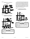
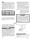
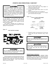
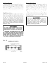
Single Stage Thermostat Operation:
The automatic heat staging option allows a single stage
thermostat to be used with a two stage furnace. To
activate this option, move the jumper pin (see Figure 11)
to desired setting (5 minutes or 10 minutes). The furnace
will start on first (1
ST
) stage heat and stay at first (1
ST
)
stage heat for the duration of the selected time before
switching to 2
nd
stage heat.
20571201 Issue 0527 Page 15 of 28