


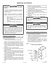

STARTUP AND OPERATIONAL CHECKOUT
It is not recommended that this furnace be used as
a construction heater during any phase of
construction. Very low return air temperatures,
harmful vapors and operation of the unit with
clogged or misplaced filters will damage the unit.
The unit may only be used for heating of buildings
or structures under construction, if the conditions
listed on page 6 in the "Introduction" section of
these instructions are met.
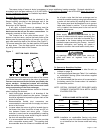
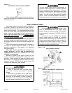
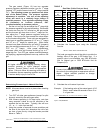
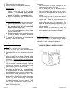
The automatic gas valve controls the flow of gas to
the main burners. The control circuit built into the
automatic valve body has 2 positions: "OFF" and "ON"
(Figure 13). To shut off gas manually: Switch from "ON"
to "OFF" position. When in "OFF" position, the main
burners are extinguished.
This furnace is equipped with an automatic hot-
surface ignition control and does not require the manual
lighting for furnace operation.
Figure 13
GAS CONTROL DIAGRAM
Do not attempt to manually light the burners.
Failure to follow this warning can lead to electrical
shock that could result in bodily harm.
After the ductwork connections have been made, gas
piping and electrical wiring completed and the furnace
has been properly vented, the unit should be started and
adjusted for proper operation. Check off the following
steps as they are completed.
1. Be sure all electrical power is OFF.
2. Check all wiring using proper wiring diagram on
inside of the control box cover.
3. Turn ON the electrical power.
4. Set the ignition system control switch in the "ON"
position.
5. Set the thermostat above room temperature.
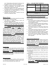
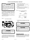
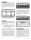
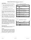
6. The hot-surface ignitor will heat-up to an "orange"
glow, the main burners will ignite.
Figure 14
TYPICAL FLAME APPEARANCE
(Main Burners)
7. Recheck for leaks in the manual shut off valve, gas
control valve and gas connections using a soap
solution.
Never use an open flame when testing for gas
leaks! Use of an open flame could lead to a fire or
explosion.
Many soaps used for leak testing are corrosive to
certain metals. Piping must be rinsed thoroughly
with clean water after leak check has been
completed.
Manifold Pressure Adjustment:
Turn OFF the gas and electrical before
preceeding! Remove the manifold pressure tap pipe
plug from the gas valve (Figure 13 outlet pressure tap)
and install a pressure tap and connect it to a manometer.
Turn on the gas and electrical supplies.
20571201 Issue 0527 Page 19 of 28