


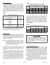

This furnace is manufactured for use with Natural gas
and must be converted using the proper LP conversion kit
for use with LP (Propane) gas. For LP (Propane) gas, a
tank regulator is required to reduce supply pressure to
12"-13"w.c. For manifold pressure see Table 6.
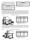
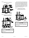
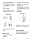
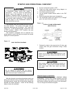
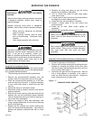
A main manual shut off valve must be used in the
gas piping. The shut off type and location must follow
local codes and should always be in an accessible but
protected location. In the absence of local codes the
recommended methods for installing the gas piping to the
furnace are shown in Figures 12-A and 12-B.
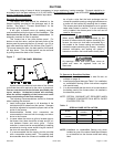
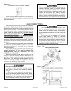
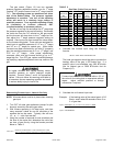
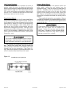
The gas valve contains two threaded ports for a 1/8"
NPT tap in order to test incoming gas pressure and
outgoing manifold pressure (See Figure 13).
Many soaps used for leak testing are corrosive to
certain metals. Piping must be rinsed thoroughly
with clean water after leak check has been
completed.
Never use an open flame when testing for gas
leaks! Use of an open flame could lead to a fire or
explosion.
CONTROL BOARD & VARIABLE SPEED MOTOR FEATURES
Humidifier Connections:
Terminals are provided on the blower control board
for connections to a 120-volt optional humidifier. The
"HUM" terminal is energized whenever the thermostat
calls for heat. Refer to furnace wiring diagram for specific
connection information.
Electronic Air Cleaner Connections:
Terminals are provided on the blower control board
for connection of a 120-volt optional electronic air cleaner.
The "EAC" terminal is energized whenever the thermostat
calls for heat, cooling, or continuous blower. Refer to the
furnace wiring diagram for specific connection information.
Continuous Blower Operation:
The comfort level of the living space can be
enhanced when using this feature by allowing continuous
circulation of air between calls for cooling or heating. The
circulation of air occurs at half the full cooling airflow rate.
To engage the continuous blower operation, place the
fan switch on the thermostat into the ON position. A call
for fan from the thermostat closes R to G on the ignition
control board. The control waits for a 1 second
thermostat debounce delay before responding to the call
for fan by ramping the circulating blower up to 50% of the
cooling speed, but not less than 425 cfm's. When the call
for continuous fan is satisfied, the control immediately de-
energizes the circulating blower.
Dehumidification:
For situations where humidity control is a problem, a
dehumidification feature has been built into the variable
speed motor. At the start of each cooling cycle, the
variable speed motor will run at 82% of the rated airflow
for 7.5 minutes. After 7.5 minutes has elapsed, the motor
will increase to 100% of the rated airflow.
Additional dehumidification can be achieved by
connecting a humidistat to the DEHUM and R terminals
on the integrated ignition/blower control board. In this
setup, the variable speed motor will operate at a 10%
reduction in the normal cooling airflow rate when there is
a call for dehumidification.
Both dehumidification methods described above can
be utilized on the same furnace.
Variable Speed Features:
The furnace is equipped with a variable speed
circulation air blower motor that will deliver a constant
airflow within a wide range of external static pressures.
Other features of this variable speed motor include:
Soft Start:
The variable speed motor will slowly ramp up to
normal operating speed. This minimizes noise and
increases comfort by eliminating the initial blasts of air
encountered with standard motors.
Soft Stop:
At the end of a cooling or heating cycle, the variable
speed motor will slowly ramp down after a short blower
"off" delay. If continuous blower operation has been
selected, the variable speed motor will slowly ramp down
until it reaches the airflow for that mode.
Circulating Airflow Adjustments
Heating Mode:
The unit, as shipped, is factory set (setting "A") to run
at the middle of the heating rise range as shown on the
unit rating plate. Adjustments can be made to the heating
airflow by repositioning the jumper plug marked HEAT-A,
B, C, D (see AirFlow Adjustment Table on page 4) based
on the information found in the table. Heating rise must
always be within the rise range shown on the rating
plate.
20571201 Issue 0527 Page 17 of 28