


DUCTING
The proper sizing of warm air ducts is necessary to insure satisfactory heating operation. Ductwork should be in
accordance with the latest editions of (U.S.) NFPA-90A (Air Conditioning Systems) and NFPA-90B (Warm Air Heating
and Air Conditioning Systems) or Canadian equivalent.
Ductwork Recommendation:
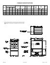
The supply duct work should be attached to the
flanged opening provided at the discharge end of the
furnace. See page 3 "Furnace Specificatons" for the
dimensions of this opening.
A left, right, or bottom return air opening must be
used as determined by the layout of the installation. The
back must not be cut out for return connections. An
externally mounted air filter is required.
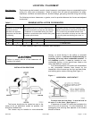
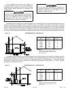
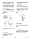
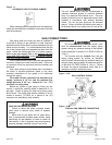
This furnace has a two piece bottom panel. For
bottom or end duct return, remove the back portion of the
bottom panel by removing the four (4) screws - two (2) on
each side toward the back of the furnace (See Figure 7).
Tilt furnace toward the front, the back portion of the panel
will drop down. Then the back portion can be removed
by pulling toward the back of the furnace.
Figure 7
BOTTOM PANEL REMOVAL
Knockouts are provided on both sides of the furnace
to facilitate the cutout required to the return air ductwork.
Furnace cutouts must be the full size specified by the
corner markers. Undersized cutouts will adversely
affect the airflow capability of the furnace and could
cause overheating of the heat exchanger.
The following recommendations should be followed
when installing the ductwork:
1. Install locking-type dampers in all branches of the
individual ducts to balance out the system. Dampers
should be adjusted to impose the proper static at the
outlet of the furnace.
2. Noncombustible flexible duct connectors are
recommended to connect both the supply and return
ducts to the furnace.
3. In cases where the return air grille is located close to
the blower inlet, there should be at least one 90° air
turn between blower and return grille. Further
reduction in sound can be accomplished by installing
acoustical air turning vanes and/or lining the inside of
the duct with acoustical material.
4. It is recommended that the supply duct be provided
with a removable access panel. This opening shall
be accessible when the furnace is installed and shall
be of such a size that the heat exchanger can be
viewed for possible openings using light assistance or
a probe can be inserted by sampling the air stream.
The access panel shall be designed so as to prevent
leaks when locked in position. If an air conditioning
coil is installed, the access panel to the coil can be
used for this purpose.
When supply ducts carry air circulated by the
furnace to areas outside the spaces containing the
furnace, the return air shall also be handled by a
duct sealed to the furnace casing and terminating
outside the space containing the furnace. Incorrect
ductwork termination and sealing will create a
hazardous condition that could lead to bodily harm.
Air openings, intake and outlet pipes, return air
grilles and warm air registers must not be
obstructed.
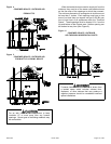
To Convert to Downflow Position:
1. Convert the combustion blower to side flue exit, as
outlined on page 14.
2. Install proper special base per Table 2 for installation
on combustible flooring (follow instructions supplied
with special base).
3. It is recommended that the return air be connected to
the bottom panel of the furnace when it is installed in
the downflow position.
NOTE: SPECIAL SUB-BASE NOT REQUIRED WHEN
FURNACE IS MOUNTED ON A METAL CASED
EVAPORATOR COIL.
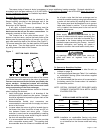
Table 2
SPECIAL BASE INSTALLATION
MODEL
SPECIAL BASE
NUMBER
CAT. NO.
AV050B3
AV075B3
20066501 68L77
AV100B4 20066502 68L78
AV125B5 20066503 68L79
NOTE: Installation on combustible flooring only when
installed on one of the above listed special bases
or as identified on the furnace model and rating
label.
20571201 Issue 0527 Page 11 of 28