


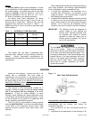


Cooling Mode:
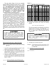
The units are factory set for the highest airflow for
each model. Adjustments can be made to the cooling
airflow by repositioning the jumper plug marked COOL -
A, B, C, D (see AirFlow Adjustment Table on page 4)
based on the information found in the table.
By moving the ADJUST jumper plug (see Table on
page 4) from the NORM position to the (+) or (-) position
will also cause the cooling airflow setting to be raised or
lowered by 15%.
The TEST position on the ADJUST tap is not used.
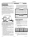
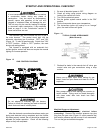
To determine what CFM the motor is delivering at any
time, count the number of times the amber LED on the
control board flashes. Each flash signifies 100 CFM;
count the flashes and multiply by 100 to determine the
actual CFM delivered (for example: 10 flashes x 100 =
1000 CFM).
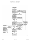
UNIT SEQUENCE OF OPERATION
Here's How Your Heating System Works:
Standby Mode
When the control is in standby mode, it continually
monitors thermostat input, rollout switch, and flame
sense.
Call For Heat
On a call for 1
st
stage heat (W1) from the room
thermostat, the ignition control performs a 1-second self-
check. The control verifies the limit switch is closed and
both low and high pressure switches are open. The
control always starts on low-fire and ignores 2
nd
stage call
for heat until low heat is established and heat blower on
delay is complete. The induced draft blower is energized
to high speed and waits for the low pressure switch to
close before starting a 15-second pre-purge period. Upon
completion of the pre-purge the hot surface igniter is
energized for a period of 7 seconds (15 seconds on
retries) before the gas valve is energized on 1
st
stage and
main burners ignite. The induced draft blower remains on
high speed with the gas on low fire for the first 15
seconds of steady heat and ignores any 2
nd
stage
demand. After the 15 second period the control switches
the inducer to low speed. After a 30 seconds blower "on"
delay, the control energizes the low heat circulating air
blower. The blower runs at reduced CFM (approximately
400 CFM) for 30 seconds then ramps up to 1
st
stage heat
speed.
If 1
st
stage heating operation is not sufficient to satisfy
the heating demand, the room thermostat initiates a call
for 2
nd
stage heat (W1 and W2). The control changes the
inducer from low to high speed and confirms the high-fire
pressure switch contacts are closed and the gas valve
energizes on 2
nd
stage heat. The circulating air blower
then ramps up to 2
nd
stage heat speed.
When the 2
nd
stage call for heat is satisfied, the
control shuts off the gas valve and runs the combustion
air blower for a post purge period of 5 seconds. The
circulating air blower continues to run for approximately 3
minutes before ramping down. If the thermostat W2 call
ends and W1 remains, the control de-energizes the high
gas output, changes the inducer speed from high to low
and the gas valve drops back to 1
st
stage heat. After
approximately 2 minutes the circulating air blower ramps
down to 1
st
stage heat speed.
In the event the unit loses ignition, the control will
attempt to recycle up to five times before it goes into a 1-
hour lockout. Lockout may be manually reset by
removing power from the control for more than 1 second
or removing the thermostat call for heat for more than 3
seconds.
If during a heating cycle the limit control senses an
abnormally high temperature and opens, the ignition
control de-energizes the gas valve and the combustion
blower while the circulating blower ramps up to 2
nd
stage
heat speed. The circulating blower remains energized
until the limits are closed.
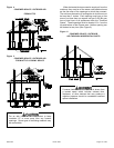
Should overheating occur, or the gas supply fail to
shut OFF, turn OFF the manual gas valve to the
appliance BEFORE turning OFF the electrical
supply. A failure to adhere to this warning can
result in a fire or explosion and bodily harm.
Fan "ON"
A call for continuous fan from the thermostat closes
R to G on the control board. The control waits for a 1-
second debounce delay before responding by energizing
the circulating air blower at 50% of the cooling speed.
When the call for fan is turned off, the control de-
energizes the circulating blower.
Cooling
A call for cooling from the thermostat closes R to Y
and R to G on the blower control board. The control
waits for a 1-second thermostat debounce delay before
energizing the circulating air blower to 82% of the cooling
speed. After 7.5 minutes, the circulating blower
automatically ramps up to 100% of the cooling speed.
When a call for cooling is satisfied, the circulating blower
ramps back down to 82% of the cooling speed for 60
seconds then shuts off.
20571201 Issue 0527 Page 18 of 28