


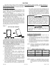


Filters:
Air filters must be used in every installation. For side
return installations, air filters must be installed external to
the furnace casing. An external filter rack kit with filter
(parts No. 20069901 or Cat. No. 68L75 12 / 15½" x 25"
sizes and 20069902 or Cat. No. 68L76 for 15½" / 19" x
25" sizes) is available as an optional accessory.
For bottom (end) return installations, the above
optional external rack may be used, if the unit was not
provided with a internal filter. Minimum filter size and
suggested filter materials are shown in Table 3. (If
different type filter is used, it must be an equivalent high
airflow capacity.)
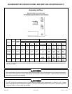
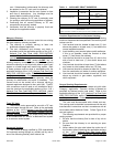
Table 3 EXTERNAL FILTER RACK SIZE
MODEL
SIDE
RETURN
BOTTOM/END
RETURN
050-3
075-3
15 ½ X 25 12 X 25
100-4 15 ½ X 25 15 ½ X 25
125-5 15 ½ X 25 19 X 25
This furnace may use either a disposable filter,
permanent filter, electronic or high efficiency media air
cleaner. Consult filter/cleaner manufacturers for
maintience service and static pressure drop for air moving
requirements.
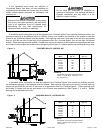
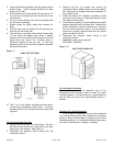
When installing the furnace with cooling equipment for
year round operation, the following recommendations
must be followed for series or parallel air flow:
1. In series flow applications, the evaporator coil is
mounted after the furnace in an enclosure in the
supply air stream. The furnace blower is used for
both heating and cooling airflow.
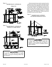
2. In parallel flow installation, dampers must be provided
to direct air over the furnace heat exchanger when
heat is desired and over the cooling when cooling is
desired. At no time may the evaporator coil be
located on the return air side of the heat exchanger.
IMPORTANT: The dampers should be adequate to
prevent cooled air from entering the
furnace, and if manually operated, must
be equipped with means to prevent
operation of either the cooling unit or
furnace unless the damper is in the full
cool or full heat position.
The coil MUST be installed on the air discharge
side of the furnace. Under no circumstances
should the air flow be such that cooled, conditioned
air can pass over the furnace heat exchanger. This
will cause condensation in the heat exchanger and
possible failure of the heat exchanger that could
lead to a fire hazard and/or hazardous conditions
that may lead to bodily harm. Heat exchanger
failure due to improper installation will not be
covered by warranty.
VENTING
Venting for this category I furnace must be to the
outside and in accordance with local codes or
requirements of the local utility. In the absence of local
codes, venting must conform to the applicable sections of
the latest edition of the (U.S.) National Fuel Gas Code
ANSI Z223.1/NFPA54, and/or CSA B149.1 Natural Gas
and Propane Installation Codes, and the vent
manufacturers instructions.
This furnace is CSA International certified as a
Category I forced air appliance and can not be vented
into a vent system with any Category II, III or IV
appliance. It must be vented vertically, or nearly
vertically, unless installed with a listed mechanical venter
in accordance with horizontal venting instructions. It must
not be connected to any portion of a mechanical draft
system operating under positive pressure
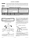
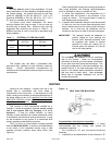
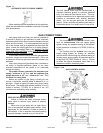
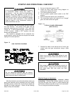
The 3" (in.) to 4" (in.) vent adaptor coupling (supplied
with unit) MUST BE USED. It must be connected directly
to the outlet of the combustion blower using a field
supplied corrosion resistant sheet metal screw (See
Figure 8).
Figure 8
VENT ADAPTOR MOUNTING
Pre-Installation Vent System Inspection:
Before this furnace is installed, it is highly
recommended that any existing vent system be
completely inspected.
For a chimney or "B" vent, this should include the
following:
1. Inspection for any deterioration in the chimney or "B"
20571201 Issue 0527 Page 12 of 28