


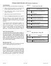

4. Disconnect wires from rollout switch.
5. Remove manifold or burner/manifold assembly.
Manifold ONLY
a. Remove the No. 10 screws that secure the
manifold pipe to both legs of the manifold
assembly. The manifold pipe must be
supported during this step, or it could fall and
damage the furnace or cause bodily injury!
b. Slide the manifold pipe (with valve and orifice)
forward, out of the furnace.
Burner/Manifold Assembly
a. Remove the No. 10 screws that secure the
burner/manifold assembly legs to the furnace.
The manifold pipe must be supported during
this step, or it could fall and damage the
furnace or cause bodily injury!
b. Slide the burner/manifold assembly forward, out
of the furnace until the assembly is clear of the
manifold retention pins.
c. Rotate the assembly slightly, in order for the legs
to clear the sides of the cabinet, and remove
through the front of the furnace.
8. To reinstall the manifold pipe or burner/manifold
assembly, reverse the above steps.
Blower Removal/Replacement:
Removal
1. Turn OFF all electrical power to the furnace.
2. Remove the control box access panel and blower
access panel.
3. Unplug wires from the blower assembly to the control
box.
4. Remove the four (4) screws securing the control box
in the unit (two (2) in the cabinet at the sides of the
blower door opening and two (2) at the top rear of the
control box). Be sure to support the control box so
that it does not fall!
5. Rotate the control box out of the cabinet and support
it so that no strain is placed on any wiring. It may be
necessary to disconnect the electrical supply and
thermostat wiring from the control board.
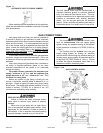
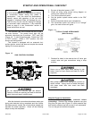
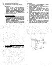
6. Remove the blower retaining screws from the front of
each blower leg (See Figure 18). These are the two
(2) screws located in the blower compartment that
secure the blower legs to the blower partition panel.
7. Slide the blower forward about two (2) inches. This
will disengage the rear of the blower legs from the
blower partition. Rotate the front of the blower down
to clear the control box mounting tabs on the
underside of the blower partition, and continue sliding
the blower forward until it is out of the unit. Take
care to clear the control box mounting tabs. If
necessary, disconnect the auxiliary limit leads on the
sides of the blower housing.
Replacement
1. Place the blower in the blower opening of the unit
and reconnect the auxiliary limit leads.
2. Slide the blower back, into the unit, taking care to
clear the control box mounting tabs.
3. When the blower is about halfway into the cabinet,
rotate the rear of the blower UP so that the rear of
the blower legs engage the side rails in the blower
partition.
4. Continue sliding the blower into the unit until the front
of the blower housing is behind the control box
mounting tabs. Rotate the front of the blower UP
until the legs lie flat against the bottom of the blower
partition, then slide blower fully into position. The
rear of the blower should be against the stop in the
partition and the rear of the blower legs should be
under the partition.
5. Reattach the two (2) blower securing screws, the
control box, any disconnected wiring, the blower
access panel, and the control box access panel.
Lubricating Motors:
Direct drive motor and blower assemblies are factory
lubricated and normally do not require oiling. If oiling is
required lubrication of the blower motor is to be
preformed only by a qualified service agency.
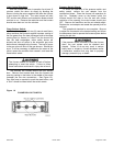
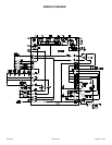
Figure 18
BLOWER REMOVAL AND REPLACEMENT
20571201 Issue 0527 Page 25 of 28