


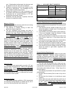

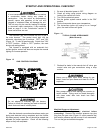
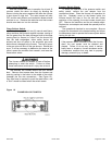
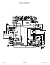

The gas control (Figure 13) has two separate
pressure regulator adjustment screws, one for 1
st
stage
(marked "LO") and the second one for 2
nd
stage (marked
"HI"). The adjusting screws are positioned on either
side of the barbed fitting. The pressure regulator
adjustment is sensitive: one turn of the adjusting
screw will result in a relatively large change in
manifold pressure. Turn regulator-adjusting screws
IN (clockwise) to increase pressure, OUT
(counterclockwise) to decrease presure.
Set the unit on high fire and adjust the 2
nd
stage high
fire pressure regulator to the required setting. Disconnect
the violet wire from the "HI" terminal on the gas control
and the burners will drop down to the 1
st
stage low fire,
then adjust the 1
st
stage pressure regulator setting as
required. Gas input must never exceed the value shown
on the furnace rating label. These units are equipped for
rated input at manifold pressures of 2.3" w.c. (1
st
stage)
and 3.5" w.c. (2
nd
stage) for natural gas. When these
furnaces have been converted for use with LP (propane)
gas, the manifold pressures are 6.4" w.c. (1
st
stage) and
10.0" w.c. (2
nd
stage). After proper adjustments,
reconnect violet wire and furnace should go up to 2
nd
stage high fire. Turn OFF gas, replace manifold pressure
tap pipe plug, regulator adjustment vent cap, and turn ON
gas.
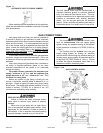
At higher altitudes and varying heating valves,
manifold pressure or orifice changes maybe
required. Consult Tables 7 and 8 for appropriate
values. Failure to follow this warning could lead to
a hazardous furnace operating condition and result
in serious bodily injury or loss of life.
Determining Furnace Input - Natural Gas Only
NOTE: All access doors must be in place when checking
gas input.
1. Turn OFF all other gas appliances (except for pilot
burners) served by the same gas meter.
2. With furnace operating in full heat cycle, note how
many seconds it takes for one full revolution of the
smallest dial on the meter. Typically, this will be a
1/2 - or - 1 - cubic foot test dial.
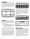
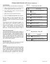
3. Using the number of seconds for one revolution and
the size of the meter dial, determine the cubic foot
per hour of gas flow by using the formula provided
below or Table 5.
Cubic Ft/Hr =
Number of Dial Revolutions x Cubic Foot/Revolution x 3600
Time (in seconds) Required for Number of Timed Revolutions
TABLE 5
Gas Rate (Cubic Feet per Hour)
Seconds for
One
Revolution
TEST DIAL
1/2
Cubic
Feet
1
Cubic
Foot
2
Cubic
Feet
10 160 360 720
12 150 300 600
14 129 257 514
16 113 225 450
18 100 200 400
20 90 180 360
22 82 164 325
24 75 150 300
26 69 138 276
28 64 129 258
30 60 120 240
32 56 113 226
34 53 106 212
Seconds for
One
Revolution
TEST DIAL
1/2
Cubic
Feet
1
Cubic
Foot
2
Cubic
Feet
36 50 100 200
38 47 95 190
40 45 90 180
42 43 86 172
44 41 82 164
46 39 78 156
48 37 75 150
50 36 72 144
52 35 69 138
54 34 67 134
56 32 64 128
58 31 62 124
60 30 60 120
4. Calculate the furnace input using the following
formula:
BTUH = Cubic Ft/Hr x BTU/Cubic Foot
The local gas supplier should be able to provide the
heating value of the gas, in BTU/cubic foot. If a
specific value is not available, use 1000 BTU/cubic
foot for Natural gas or 2500 BTU/cubic foot for
Propane (LP).
Furnace input should be maintained within ± 2% of
the value on the rating plate or appropriate altitude
derate. Adjust manifold pressure or change
orifices size if required.
5. Calculate the unit's actual input rate.
Example: If the heating value of the natural gas is 1015
Btu/cu. and it takes 60 seconds to burn 2 cu.
ft. of gas then:
Input = 1015 Btu/cu. ft. X 1 rev X 2 cu. ft./rev. X 3600
60 sec.
Input = 121,800 Btu/hr.
20571201 Issue 0527 Page 20 of 28