


9
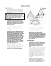
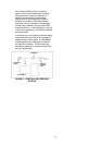
vibration, and bearing loads that result in
premature bearing failure and ultimate seizing
of the pump. Misalignment can be angular,
parallel, or a combination of these, and in the
horizontal and vertical planes. Final alignment
should be made by moving and shimming the
motor on the base plate, until the coupling
hubs are within the recommended tolerances
measured in total run-out. All measurements
should be taken with the pump and motor foot
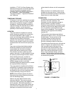
bolts tightened. The shaft of sleeve bearing
motors should be in the center of its
mechanical float.
NOTE: Proper alignment is essential for
correct pump operation. This should be
performed after base plate has been properly
set and grout has dried thoroughly according
to instructions. Final alignment should be
made by shimming driver only. Alignment
should be made at operating temperatures.
WARNING: Unexpected Start-up Hazard
Disconnect and lock out power before
servicing. Failure to follow these instructions could
result in serious personal injury or death and
property damage.
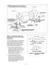
ANSI/OSHA COUPLER GUARD
REMOVAL/INSTALLATION
WARNING: Unexpected Start-up Hazard
Disconnect and lock out power before
servicing. Failure to follow these instructions could
result in serious personal injury or death and
property damage.
NOTE: Do not spread the inner and outer
guards more than necessary for guard
removal or installation. Over spreading the
guards may alter their fit and appearance.
Removal
a. Remove the two capscrews that hold the
outer (motor side) coupler guard to the
support bracket(s).
b. Spread the outer guard and pull it off the
inner guard.
c. Remove the capscrew that holds the inner
guard to the support bracket.
d. Spread the inner guard and pull it over the
coupler.
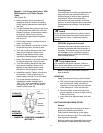
Installation
a. Check coupler alignment before
proceeding. Correct if necessary.
b. Spread the inner guard and place it over
the coupler.
c. With the inner guard straddling the
support bracket, install a capscrew
through the hole (or slot) in the support
bracket and guard located closest to the
pump. Do not tighten the capscrew.
d. Spread the outer guard and place it over
the inner guard.
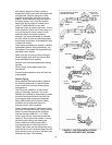
e. Install the outer guard capscrews by
following the step stated below which
pertains to your particular pump:
i. For pumps with a motor saddle support
bracket: Ensure the outer guard is
straddling the support arm, and install
but do not tighten the two remaining
capscrews.
ii. For pumps without a motor saddle
support bracket: Insert the spacer
washer between the holes located
closest to the motor in the outer guard,
and install, but do not tighten, the two
remaining capscrews.
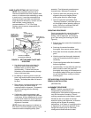
f. Position the outer guard so it is centered
around the shaft, and so there is less than
a 1/4" of the motor shaft exposed. On
guards that utilize a slotted support
bracket, the inner guard will have to be
positioned so there is only a 1/4" of the
pump shaft exposed.
g. Holding the guard in this position, tighten
the three capscrews.