


30
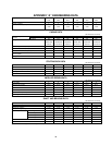
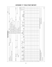
APPENDIX “A” ENGINEERING DATA
Pump Size A
8x6x14F-S
8200
H8x6x14F-S
8200
8x6x14F-L
8200
H8x6x14F-L
8200
8x6x18
8200
H8x6x18
8200
Number of Stages 2 2 2 2 2 2
Approval Flow Rate (GPM) 500/750
/1000
500/750
/1000
500/750
/1000
500/750
/1000
500/750
/1000
500/750
/1000
CASING DATA
(All Dimensions in Inches)
Suction 125 or 250 125 or 250 125 or 250 125 or 250 125 250
Flange Rating ASA
Standard
Discharge 250 800 250 800 250 250
Casing Material
Cast Iron
ASTM A48
Class 35
Ductile Iron
ASTM A536
Gr. 65-45-12
Cast Iron
ASTM A48
Class 35
Ductile Iron
ASTM A536
Gr. 65-45-12
Cast Iron
ASTM A48
Class 35
Ductile Iron
ASTM A536
Gr. 65-45-12
Max. Working Pressure (PSIG) 500 800 500 800 375 500
Max. Suction Pressure (PSIG) 100 300 100 300 100 200
Max. Hydrostatic Pressure (PSIG) 750 1200 750 1200 563 750
Standard Hydrostatic Test
Pressure (PSIG)
625 1000 625 1000 468 625
Casing Wall Thickness .75 .75 .75 .75 .75 .75
STUFFING BOX DATA
(All Dimensions in Inches)
Bore 3.75 3.75 3.75 3.75 3.75 3.75
Depth 4.06 4.06 4.06 4.06 4.06 4.06
Packing: No. Rings/Size Square 5/.50 5/.50 5/.50 5/.50 5/.50 5/.50
Seal Cage Width .94 .94 .94 .94 .94 .94
Shaft Sleeve O.D. 2.75 2.75 2.75 2.75 2.75 2.75
IMPELLER DESIGN DATA
(All Dimensions in Inches)
No. of Vanes 6 6 6 6 6 6
Inlet Area (Sq. Inches) 26.75 26.75 33.14 33.14 28.72 28.72
Maximum Diameter 14.0 14.0 14.0 14.0 18.0 18.0
Minimum Diameter 9.0 9.0 9.0 9.0 13.5 13.5
Maximum Sphere .50 .50 .63 .63 .63 .63
WR for Max. Dia. (Lbs-Ft) 8.5 8.5 8.0 8.0 20.0 20.0
Wear Ring Clearance - Diametral .015-.017 .015-.017 015-.017 015-.017 015-.017 015-.017
SHAFT AND BEARING DATA
(All Dimensions in Inches)
Diameter Thru Impeller 2.437 2.437 2.437 2.437 2.437 2.437
Diameter Thru Sleeve 2.375 2.375 2.375 2.375 2.375 2.375
Diameter at Coupling 2.125 2.125 2.125 2.125 2.125 2.125
Shaft Span – Brg. to Brg. 33.45 33.45 33.45 33.45 33.45 33.45
Inboard Brg. No. 5311 5311 5311 5311 5311 5311
Dia. Thru Brg. 2.1654 2.1654 2.1654 2.1654 2.1654 2.1654
Outboard Brg. No. 7311 BG (2) 7311 BG (2) 7311 BG (2) 7311 BG (2) 7311 BG (2) 7311 BG (2)
Ball Bearings
Dia. Thru Brg. 2.1654 2.1654 2.1654 2.1654 2.1654 2.1654
Frame Number F27-A1 F27-A1 F27-A1 F27-A1 F27-A1 F27-A1
Instruction Book Number AC2675 AC2675 AC2675 AC2675 AC2675 AC2675
A (H) Prefix indicates High Pressure Casing