


29
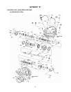
24. Assemble rotating element in lower half
casing. Correctly locate casing ring pins,
stuff box bushing pins, and interstage
diaphragm pins in casing main joint slots.
Sliding the inboard bearing housing
towards the coupling slightly will ease
assembly.
25. Bolt outboard bearing housing in place. Be
sure that both housings are seated
properly in lower half casing.
26. Bolt inboard bearing housing in place.
Rotating element should now turn freely.
CAUTION:
Double check rotation of pump before
installing the upper half casing. Failure to follow
these instructions could result in injury or property
damage.
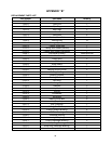
27. Lower the upper half casing (2-001-7) into
place, locate using the dowels (2-916-0),
and install casing main joint bolts (2-904-
1). The casing joint bolts should be
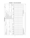
tightened to the torque specified in Figure
16.
NOTE: Torque values are essential in
obtaining proper gasket compression so no
leakage can occur at main joint.
28. Slide deflectors toward bearing covers.
Allow rotating clearance of approximately
1/16".
29. Rotate shaft by hand to assure that it turns
smoothly and is free from rubbing and
binding.
30. Cut full rings packing (1-924-9) so that
ends butt, leaving no gap between
packing and casing. Install three rings of
packing and tap fully to bottom of both
stuffing boxes. Stagger joints of each ring
of packing at least 90°. Install seal cage
(1-013-9) and be sure that it will line up
with seal water inlet when packing is
compressed. Install remaining two rings of
packing with joints staggered. Assemble
glands (1-014-9) square with stuffing box
and pull up tight. Then loosen gland bolts
(1-904-9) to permit packing to expand,
and retighten finger tight. Final adjustment
of gland bolts must be done when pump is
running. Allow 30 minutes between
adjustments.
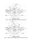
31. Assemble seal water flush and bleed lines
(1-952-0).
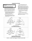
a) Clockwise – Figure 11
b) Counter-clockwise – Figure 12
32. Check coupling alignment and realign if
necessary.