


7
installation. ITT AC Fire Pump Systems has
determined that proper and correct alignment
can only be made by accepted erection
practices. Refer to the following paragraphs
on “Foundation,” “Base Plate Setting,”
“Grouting Procedure,” “Alignment Procedure”
and “Doweling.”
TEMPORARY STORAGE
If the pump is not to be installed and operated
soon after arrival, store it in a clean, dry place
having slow, moderate changes in ambient
temperature. Rotate the shaft periodically to
coat the bearings with lubricant and to retard
oxidation, corrosion, and to reduce the
possibility of false brinelling of the bearings.
LOCATION
The pump should be installed as near the
suction supply as possible, but no less than
five suction diameters (refer to page 11,
suction and discharge piping section) with the
shortest and most direct suction pipe
practical. The total dynamic suction lift (static
lift plus friction losses in suction line) should
not exceed the limits for which the pump was
sold.
The pump must be primed before starting.
Whenever possible, the pump should be
located below the fluid level to facilitate
priming and assure a steady flow of liquid.
This condition provides a positive suction
head on the pump. It is also possible to prime
the pump by pressurizing the suction vessel.
When installing the pump, consider its
location in relation to the system to assure
that sufficient Net Positive Suction Head
(NPSH) at pump suction is provided.
Available NPSH must always equal or exceed
the required NPSH of the pump.
The pump should be installed with sufficient
accessibility for inspection and maintenance.
A clear space with ample head room should
be allowed for the use of an overhead crane
or hoist sufficiently strong to lift the unit.
NOTE: Allow sufficient space to be able to
dismantle pump without disturbing the pump
inlet and discharge piping.
Select a dry place above the floor level
wherever possible. Take care to prevent
pump from freezing during cold weather when
not in operation. Should the possibility of
freezing exist during a shut-down period, the
pump should be completely drained, and all
passages and pockets where liquid might
collect should be blown out with compressed
air.
Make sure there is a suitable power source
available for the pump driver. If motor driven,
electrical characteristics should be identical to
those shown on motor data plate.
FOUNDATION
A substantial foundation and footing should
be built to suit local conditions. The
foundation must be substantial enough to
absorb vibration. (Hydraulic Institute
Standards recommends the foundation weigh
at least five (5) times the weight of the pump
unit.) It must form a permanent and rigid
support for the baseplate. This is important in
maintaining the alignment of the flexibly
coupled unit.
The foundation should be poured without
interruption to within 1/2 to 1-1/2 inches of the
finished height. The top surface of the
foundation should be well scored and
grooved before the concrete sets; this
provides a bonding surface for the grout.
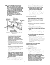
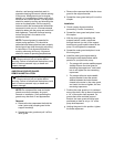
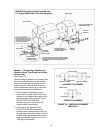
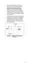
Foundation bolts should be set in concrete as
shown in Figure 5. An optional 4-inch long
tube around the bolts at the top of the
concrete will allow some flexibility in bolt
alignment to match the holes in the base
plate. Allow enough bolt length for grout,
shims, lower base plate flange, nuts and
washers. The foundation should be allowed
to cure for several days before the base plate
is shimmed and grouted.
FIGURE 5 – FOUNDATION
FOUNDATION
BOLT
PIPE SLEEVE
WASHER
BUILT-UP CONCRETE
FOUNDATION
(OPTIONAL)