


10
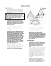
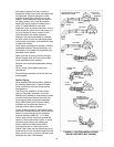
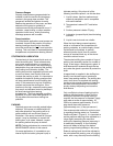
Method 1 – Straight Edge Alignment for
Standard Sleeve Type Coupler with Black
Rubber Insert
(See Figure 7A)
Proceed with this method only if satisfied that
face and outside diameters of the coupling
halves are square and concentric with the
coupling borers. If this condition does not
exist or elastomeric couplings do not make
this method convenient, use Method 2.
1. Check angular misalignment using a
micrometer or caliper. Measure from the
outside of one flange to the outside of the
opposite flange at four points 90° apart.
DO NOT ROTATE COUPLER.
Misalignment up to 1/64" per inch of
coupler radius is permissible.
2. At four points 90° apart (DO NOT
ROTATE COUPLER), measure the
parallel coupler misalignment by laying a
straight edge across one coupler half and
measuring the gap between the straight
edge and opposite coupler half. Up to a
1/64" gap is permissible.
FIGURE 7A – CHECKING ALIGNMENT
(METHOD 1)
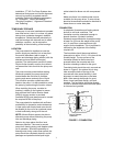
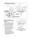
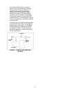
INNER GUARD
ATTACH SUPPORT BRACKET
TO BEARING HOUSING
SUPPORT
BRACKET
BRACKET
SUPPORT
BRACKET SUPPORT
ATTACHED INSIDE HERE
IN LINE WITH BOLT
CAPSCREW
FLAT WASHER
SPACER WASHER
THIS OPTION USED IN PLACE OF SPACER WHERE
OVERALL LENGTH OF GUARD EXCEEDS 12 INCHES
OR GUARD WITH IS OVER 10 INCHES ACROSS
THE FLATS.
MOTOR SADDLE
BRACKET ATTACH
TO MOTOR SADDLE
LOCKWASHER
NUT
LOCATE SUPPORT ARM
BETWEEN OUTER GUARD ENDS.
ALIGN THE ARM WITH HOLES IN
THE OUTER GUARD AND HOLES
IN THE SADDLE BRACKET.
OUTER GUARD
ANSI/OSHA Coupling Guard Exploded View
For Typical 8200 Series Fire Pump Installation
STRAIGHT EDGE
FEELER GAGE
STRAIGHT EDGE
FEELER GAGE
INCORRECT ALIGNMENT
CORRECT ALIGNMENT
ANGULAR ALIGNMENT PARALLEL ALIGNMENT