


27
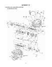
ASSEMBLY (PUMP WITH PACKING)
All bearings, O-rings, seals, gaskets, impeller
rings, and casing wear rings should be
replaced with new parts during assembly. All
reusable parts should be cleaned of all
foreign matter before reassembling. The main
casing joint gasket can be made using the
upper or lower half as a template. Lay the
gasket material on the casing joint and mark
it by pressing it against the edges of the
casing. Trim the gasket so that it is flush with
the inside edges of the casing.
NOTE: Precut casing gaskets (2-153-5, -6)
can be ordered to minimize the amount of
trimming.
1. Place impeller key (3-911-1) in shaft (3-
007-0).
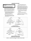
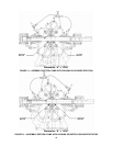
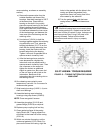
2. Identify the first and second stage
impellers (4-002-0) by the cast label. For
clockwise rotation, locate the second
stage impeller on the shaft per Figure 11
dimension ‘A’. For counter-clockwise
rotation, locate the first stage impeller per
Figure 12 dimension ‘A’.
3. Pre-assemble interstage bushing (3-034-
0) and diaphragm (3-231-0) assembly as
follows:
a) Install O-rings (3-914-7, -8) in the
three grooves on the interstage
bushing.
b) Lightly press the bushing into the
diaphragm, locating the hole in the
bushing over the pin in the diaphragm.
Install snap ring (3-915-0) to secure
assembly.
4. Slide interstage busing assembly over
shaft and place over the rear hub of the
impeller.
5. Place the other impeller on the shaft and
slide under the interstage bushing until it
touches the impeller already installed.
Verify dimension ‘A’ is maintained. See
Figure 11 or 12.
6. Apply RTV (Dow Corning Silicone Sealant
or equivalent) uniformly about shaft sleeve
(3-009-9) inside diameter, covering an
area of about 1/2 inch at each impeller
end of sleeve. Also, apply sealant to the
face of the impellers.
7. Slide shaft sleeves onto shaft, rotating the
sleeves to evenly distribute the sealant
applied in above step. Rotate until pin in
sleeve engages into keyway of impellers
and push sleeves against impeller face
until the sleeve is flush against the face.
Wipe off any excess sealant.
8. Place the sleeve O-ring (3-914-9) onto
shaft and place in sleeve counterbore.
Verify that dimension ‘A’ is maintained,
then using a pin spanner wrench and
hammer, securely tighten the shaft sleeve
nuts (3-015-9). Drill a shallow recess in
the shaft through the set screw hole in
each of the shaft sleeve nuts. Stake each
shaft sleeve nut in position with cup point
set screws (3-902-9).
9. Slide casing rings (3-003-9) onto the
impellers.
10. Place two O-rings (6-914-9) on each
stuffbox bushing (6-008-0), then slide over
shaft sleeve with the beveled end facing
the impeller.
11. Start heating bearings (3-026-3, -4) so
they will be ready to use in a later step.
Use dry heat from induction heat lamps or
electric furnace, or a 10 - 15% soluble oil
and water solution.
CAUTION:
DO NOT EXCEED 275°F. Failure to follow
these instructions could result in injury or property
damage.
CAUTION:
These are precision, high quality bearings.
Exercise care at all times to keep them clean and
free from foreign matter. Failure to follow these
instructions could result in injury or property
damage.
12. Assemble lip seal (3-177-9) in each
bearing cap (5-018-0). Seal lip or pressure
side of seal must point away from the end
of the shaft the lip seal is assembled on.
13. Slide deflectors (3-136-9) and bearing
caps on the shaft. Install snap ring (5-915-
3) on the inboard side of shaft. Install the
split ring (5-050-4) and retaining collar (5-
421-4) on the outboard side of shaft.
14. Using gloves, install the double row ball
bearing on the inboard side and locate
against snap ring.
15. Using gloves, install the two angular
contact bearings on the outboard end of
shaft. These bearings must be installed
“back to back” (wide shoulders of outer