


11
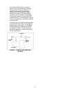
Method 2 – For Orange Hytrel Insert, 3500
RPM Operation, or All Other Coupler
Types
(See Figure 7B)
a. Make sure each hub is secured to its
respective shaft and that all connecting
and/or spacing elements are removed at
this time.
b. The gap between the coupling hubs is set
by the manufacturer before the units are
shipped. However, this dimension should
be checked. (Refer to the coupling
manufacturer’s specifications supplied
with the unit.)
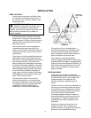
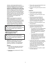
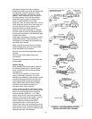
c. Scribe index lines on coupling halves as
shown in Figure 7B.
d. Mount dial indicator on one hub as shown
for parallel alignment. Set dial to zero.
e. Turn both coupling halves so that index
lines remain matched. Observe dial
reading to see whether driver needs
adjustment (See paragraph i below).
f. Mount dial indicator on one hub as shown
for angular alignment. Set dial to zero.
g. Turn both coupling halves so that index
lines remain matched. Observe dial
reading to see whether driver needs
adjustment (See paragraph i below).
h. Assemble coupling. Tighten all bolts and
set screw(s). It may be necessary to
repeat steps c through f for a final check.
i. For single element couplings, a
satisfactory parallel misalignment is
.004"T.I.R., while a satisfactory angular
misalignment is .004"T.I.R. per inch of
radius R (See Figure 7B).
FIGURE 7B – CHECKING ALIGNMENT
(METHOD 2)
Final Alignment
Final alignment cannot be accomplished until
the pump has been operated initially for a
sufficient length of time to attain operating
temperature. When normal operating
temperature has been attained, secure the
pump to re-check alignment and compensate
for temperature accordingly. See Alignment
Section.
WARNING: Rotating Components
Hazard
Do not operate pump without all guards in place.
Failure to follow these instructions could result in
serious personal injury or death and property
damage.
OPTIONAL Alignment Procedure
If desired, the pump and motor feet can be
doweled to the base after final alignment is
complete. This should not be done until the
unit has been run for a sufficient length of
time and alignment is within the tolerance.
See Doweling Section.
CAUTION: Extreme Temperature and/or
Flying Debris Hazard
Eye protection and gloves required. Failure to
follow these instructions could result in property
damage and/or moderate personal injury.
NOTE: Pump may have been doweled to
base at factory.
DOWELING
Dowel the pump and driving unit as follows:
a. Drill holes through diagonally opposite feet
and into the base. Holes must be of a
diameter 1/64 inch less than the diameter
of the dowel pins. Clean out the chips.
b. Ream the holes in feet and base to the
proper diameter for the pins (light push fit).
Clean out the chips.
c. Insert pins to be approximately flush with
feet.
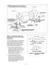
SUCTION AND DISCHARGE PIPING
General
When installing the pump piping, be sure to
observe the following precautions:
Piping should always be run to the pump.
Do not move pump to pipe. This could make
final alignment impossible.
Both the suction and discharge piping should
be supported independently near the pump
DIAL
INDICATOR
INDEX LINE
RESILIENT
SEPARATOR
DIAL
INDICATOR
ANGULAR
ALIGNMENT
PARALLEL
ALIGNMENT