


24
SERVICE INSTRUCTIONS
DISASSEMBLY AND REASSEMBLY
PROCEDURES
The procedures outlined in this section cover
the dismantling and reassembly of the 8200
Series Centrifugal Fire Pumps.
When working on the pump, use accepted
mechanical practices to avoid unnecessary
damage to parts. Check clearances and
conditions of parts when pump is dismantled
and replace if necessary. Steps should
usually be taken to restore impeller and
casing ring clearance when it exceeds three
times the original clearance.
DISMANTLING (PUMP WITH PACKING)
WARNING: Unexpected Startup Hazard
Disconnect and lockout power before
servicing. Failure to follow these instructions could
result in serious personal injury or death, or
property damage.
WARNING: Electrical Shock Hazard
Electrical connections to be made by a
qualified electrician in accordance with all
applicable codes, ordinances, and good practices.
Failure to follow these instructions could result in
serious personal injury or death, or property
damage.
WARNING:
Prior to working on pump the power source
should be disconnected with lockout provisions so
power cannot be re-energized to the motor. Close
isolating suction and discharge valves. Failure to
follow these instructions could result in property
damage, severe personal injury, or death.
CAUTION: Extreme Temperature Hazard
Allow pump temperatures to reach
acceptable levels before proceeding. Open drain
valve, do not proceed until liquid stops coming out
of drain valve. If liquid does not stop flowing from
drain valve, isolation valves are not sealing and
should be repaired before proceeding. After liquid
stops flowing from drain valve, leave valve open
and continue. Remove the drain plug located on
the bottom of the pump housing. Do not reinstall
plug or close drain valve until reassembly is
completed. Failure to follow these instructions
could result in property damage and/or moderate
personal injury.
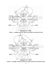
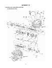
1. Drain pump by opening vent plug (2-910-
9) and removing drain plugs (2-910-9) on
suction and discharge nozzle. (See
Exploded View on page 31).
2. Remove coupling guard and separate the
coupling to disconnect the pump form the
driver.
3. Remove seal lines (1-952-0).
4. Remove gland bolts (1-904-9), washers (1-
909-9), and gland (1-014-9) from each
stuffing box.
5. Remove all casing main joint cap screws
(2-904-1) and dowels (2-916-0). Use slot
in casing main joint and separate the
casing halves with a pry bar. Lift upper
half casing (2-001-7) by castlugs.
NOTE: Casings have jacking screws.
6. Remove packing (1-924-9) and seal cage
(1-013-9) from each stuffing box.
7. Remove cap screws (3-904-9) which hold
bearing housings (3-025-3) to the casing
and lift rotating element out of lower
casing (2-001-8). Rotating element may
now be moved to suitable working
location.
8. Pull coupling half and key (3-911-2) off
shaft (3-007-0).
NOTE: A spare rotating element can be
installed at this point.
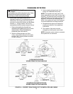
9. Remove cap screws (5-904-9) from
bearing covers (5-018-0).
10. Remove bearing housings (3-025-3),
locknut (3-516-4), and lockwasher (3-517-
4). Mount bearing puller and remove
bearings (3-026-2). Remove retaining
collar and split ring on outboard side and
snap ring on inboard side.
CAUTION:
DO NOT REUSE THE BALL BEARINGS.
Failure to follow these instructions could result in
injury or property damage.
NOTE: Locknut and lockwasher are not used
on inboard end bearing.
11. Remove bearing covers (5-018-0) and
push oil seals (3-177-9) out of bearing
covers. Pull deflectors (3-136-9) off shaft.
Slide stuff box bushings (6-008-0) off of
shaft.