


12
and properly aligned, so that no strain is
transmitted to the pump when the flange bolts
are tightened. Use pipe hangers or other
supports at necessary intervals to provide
support. When expansion joints are used in
the piping system, they must be installed
beyond the piping supports closest to the
pump. Tie bolts should be used with
expansion joints to prevent pipe strain. Do not
install expansion joints next to the pump or in
any way that would cause a strain on the
pump resulting from system pressure
changes. It is usually advisable to increase
the size of both suction and discharge pipes
at the pump connections to decrease the loss
of head from friction.
Install piping as straight as possible, avoiding
unnecessary bends. Where necessary, use
45-degree or long sweep 90-degree fitting to
decrease friction losses.
Make sure that all piping joints are air-tight.
Where flanged joints are used, assure that
inside diameters match properly.
Remove burrs and sharp edges when making
up joints.
Do not “spring” piping when making any
connections.
Provide for pipe expansion when hot fluids are
to be pumped.
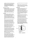
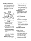
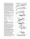
Suction Piping
When installing the suction piping, observe
the following precautions. Figure 8 shows
some correct and incorrect suction piping
arrangements.
The sizing and installation of the suction
piping is extremely important. It must be
selected and installed so that pressure losses
are minimized and sufficient liquid will flow
into the pump when started and operated.
Many NPSH (Net Positive Suction Head)
problems can be attributed directly to
improper suction piping systems.
Friction losses caused by undersized suction
piping can increase the fluid’s velocity into the
pump. As recommended by the Hydraulic
Institute Standard ANSI/HI 1.1-1.5-1994,
suction pipe velocity should not exceed the
velocity in the pump suction nozzle. In some
situations pipe velocity may need to be
further reduced to satisfy pump NPSH
requirements and to control suction line
losses. Pipe friction can be reduced by using
pipes that are one to two sizes larger than the
pump suction nozzle in order to maintain pipe
velocities less than 5 feet/second.
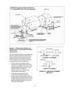
FIGURE 8 – SUCTION INSTALLATIONS
(PIPING SUPPORTS NOT SHOWN)
CHECK VALVE
GATE VALVE
INCREASER
CENTER LINE
OF PIPE
AIR POCKET
CORRECT
INCORRECT
AIR POCKET
INCORRECT
AIR POCKET
INCORRECT
GRADUAL RISE
TO PUMP
NO AIR
POC
K
ETS
GRADUAL RISE
TO PUMP
NO AIR
POCKETS
ECCENTRIC
REDUCER
CORRECT
DISTANCE PLUS
ECCENTRIC REDUCER
STRAIGNTENS FLOW
CORRECT
PATH OF WATER
INCORRECT
SUCTION PIPE INSTALLED WITH A
GRADUAL RISE TO PUMP
LEVEL
CORRECT