4
Important Safeguards (Continued)
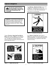
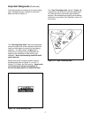
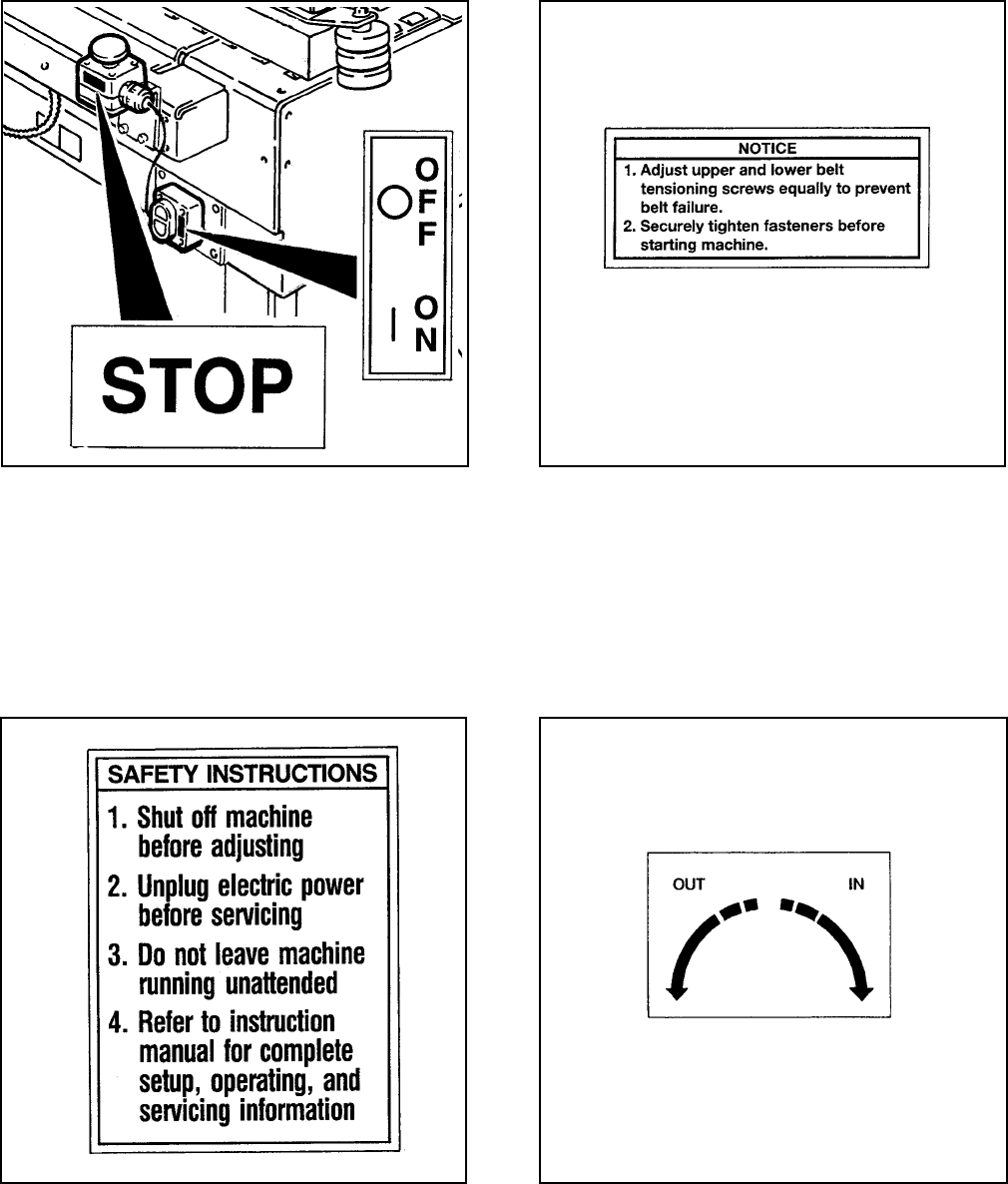
Figure 1-5 – Safety Instructions Label
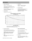
Figure 1-6 – Operating Notice Label
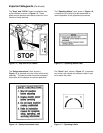
The "Stop" and "Off/On" labels, are attached next
to the switches as shown in Figure 1-4. These
labels remind operators and casual personnel of the
function of these switches.
The "Operating Notice" label, shown in Figure 1-6,
is located on top of both drive belt assemblies to
remind operators of belt adjustment procedures.
The "Safety Instructions" label, shown in
Figure 1-5, is attached to the top of the left drive belt
assembly. The label provides convenient safeguard
instructions for the operator and service personnel.
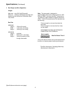
The "Out/In" label, shown in Figure 1-7, is attached
next to the crank handle that moves the belts in and
out to match box width.
Figure 1-4 – Stop and Off/On Labels
Figure 1-7 – Operating Labels


