


13
Installation and Set-Up (Continued)
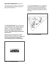
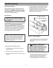
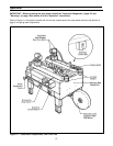
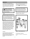
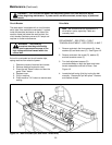
ELECTRICAL CONNECTION AND CONTROLS
The electrical control box, shown in Figure 3-1,
contains the pre-set circuit breaker and can be
located on either side of the machine frame for
customer operating convenience. A standard
three conductor power cord with plug is provided
at the back of the electrical control box for 115
Volt, 60 Hz, 1.9 Amp electrical service. The
receptacle providing this service shall be
properly grounded. Before the power cord is
plugged into 115 Volt, 60 Hz outlet, make sure
that all packaging materials and tools are
removed from the machine. Do not plug
electrical cord into outlet until ready to run
machine.
Use of an extension cord is not recommended.
However, if one is needed for temporary use, it
must have a wire size of AWG 16 [1.5 mm dia.],
have a maximum length of 30.5 m [100 ft], and
must be properly grounded.
Note – Machines outside the U.S. may be
equipped with 220/240 Volt, 50 Hz systems,
or other electrical requirements compatible
with local practice.
INITIAL START-UP OF CASE SEALER
After completing the "Installation and Set-Up"
procedure, continue through "Operation" for tape
loading and start-up to be sure case sealer is
properly adjusted to run boxes.
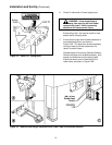
MACHINE BED HEIGHT
Adjust machine bed height. The case sealer is
equipped with four adjustable legs that are
located at the corners of the machine frame.
The legs can be adjusted to obtain different
machine bed heights from 610 mm [24 inches]
minimum to 890 mm [35 inches] maximum.
Refer to Figure 2-3C and set the machine bed
height as follows:
1. Raise and block up the machine frame to
allow adequate leg adjustment.
2. Loosen, but do not remove, two M8 x 16
socket head screws in one leg (use M6 hex
wrench). Adjust the leg length for the
desired machine bed height. Retighten the
two screws to secure the leg. Adjust all four
legs equally.
TAPE LEG LENGTH
Taping heads are pre-set to apply 70 mm
[2-3/4 inch] long tape legs. To change tape legs
to 48 mm [2 inch], see "Special Set-Up
Procedure – Changing Tape Leg Length",
page 23.
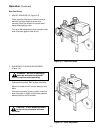
CAUTION – Machine weighs
approximately 114 kg [250 pounds]
uncrated.
8. Use appropriate material handling equipment
to remove the machine from the pallet and
move it into position.
Whenever the machine is lifted with a fork
truck, insure that the forks span completely
across the machine frame and do not contact
any wiring or mechanism under the machine
frame. In some cases the lower taping head
may need to be removed to avoid damage.
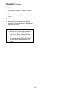
9. Continue with the remainder of the installation
and set-up procedure on this page.
TAPE WIDTH
The taping head has been pre-set to
accommodate 48 mm [2 inch] wide tape rolls.
To adjust heads for narrower tape, refer to
Section
II
, "Adjustments – Tape Web
Alignment", page 11.
WARNING – To prevent shock and
fire hazard: Position extension
cord where it will be out of the way of foot
or vehicle traffic. Extension cord is only
for temporary use – do not use for a
permanent installation.