E6581301
C-3
3
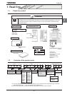
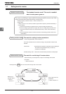
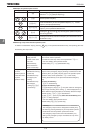
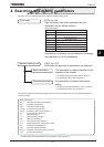
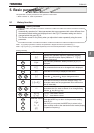
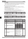
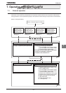
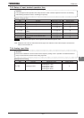
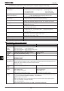
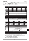
3.2 Simplified operation of the VF-AS1
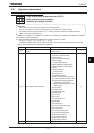
On of three operation modes can be selected: terminal board operation, operation panel and combination of both.
For other operation modes, refer to Section 5.5.
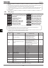
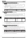
Terminal board mode
:Operation by means of external signals
Operation panel mode :Operation by pressing keys on the operation panel
Operation panel + terminal board mode :Frequency, start/stop signals can be
sent individually from the operating panel and terminal board.
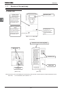
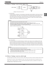
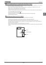
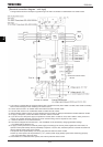
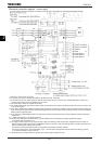
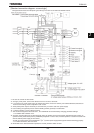
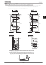
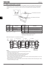
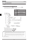
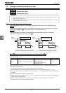
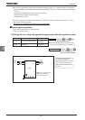
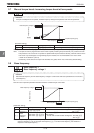
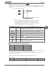
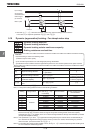
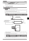
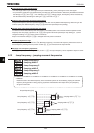
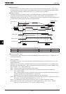
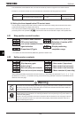
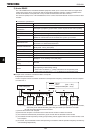
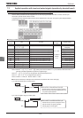
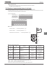
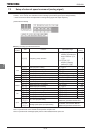
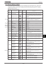
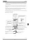
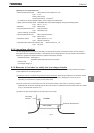
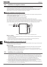
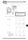
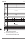
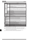
3.2.1 Terminal board operation
In this mode, the motor is started or stopped according to the ON/OFF signal to input terminals (such as the ST
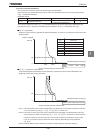
terminal and the F terminal). Also, the frequency is set according to the potentiometer/voltage/current signals to
analog input terminals (such as the RR/S4 terminal, VI/II terminal and RX terminal).
For more details, refer to Section 7.
■
■■
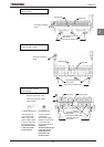
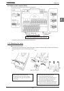
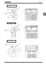
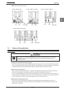
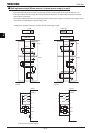
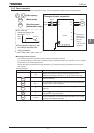
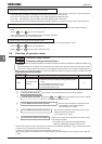
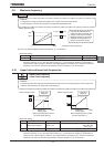
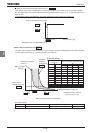
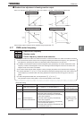
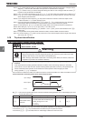
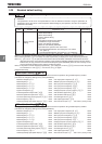
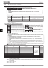
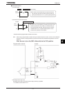
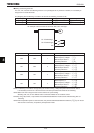
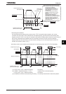
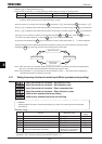
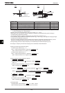
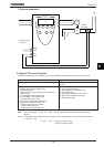
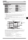
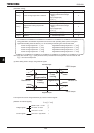
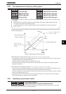
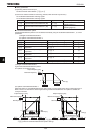
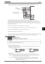
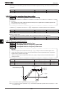
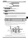
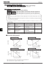
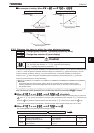
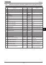
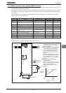
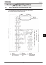
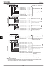
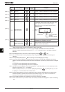
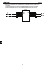
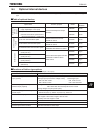
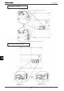
■ Example of standard connection
Motor
IM
RX
VI/II
RR/S4
PP
F
R
CC
R/L1
U/T1
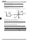
External potentiometer (or voltage signal RR/S4-CCA:0 to 10Vdc)
Voltage signal:0~10Vdc
or current signal:4(0)~20mAdc
ON:Forward run, OFF:Deceleration stop
Stand-by:ON:Stand-by, OFF:Coast stop
ST
ON:Reverse run, OFF:Deceleration stop
V/T2
W/T3
S/L2
T/L3
Power
supply
■
■■
■
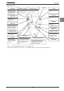
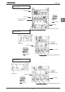
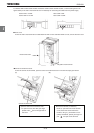
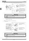
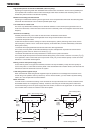
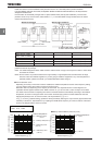
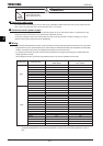
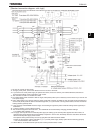
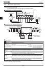
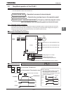
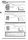
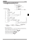
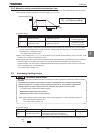
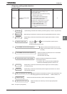
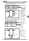
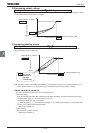
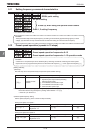
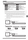
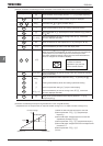
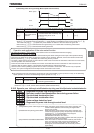
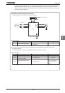
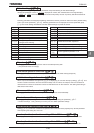
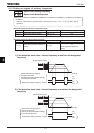
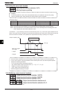
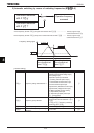
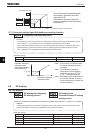
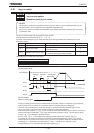
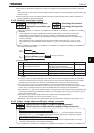
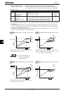
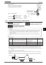
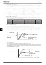
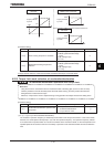
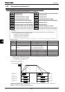
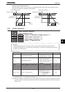
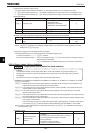
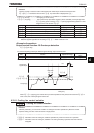
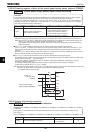
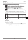
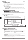
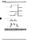
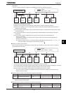
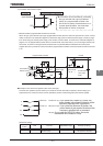
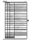
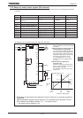
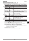
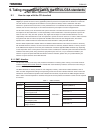
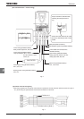
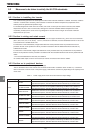
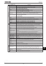
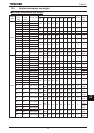
Run/Deceleration stop
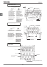
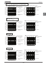
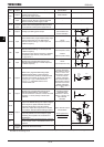
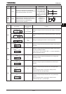
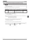
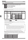
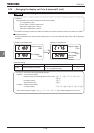
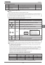
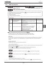
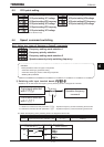
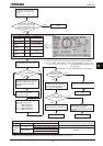
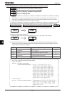
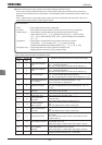
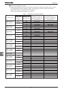
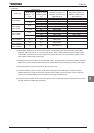
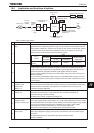
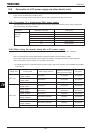
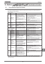
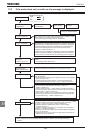
Selecting a command mode for basic parameters
EOQF
EOQFEOQF
EOQF
=
(standard default
setting)
and
are connected: Forward run
and
are disconnected: Deceleration stop
(When terminals and are electrically connected)
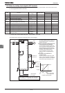
F
CC
F
CC
CCST
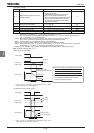
ON
OFF
ON
OFF
F-CC
ST-CC
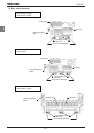
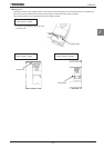
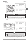
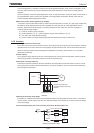
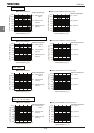
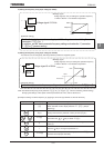
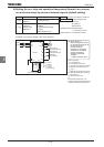
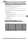
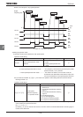
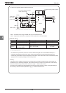
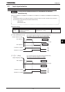
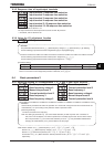
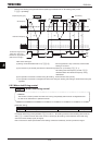
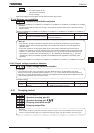
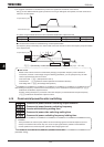
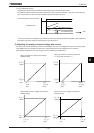
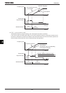
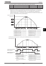
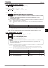
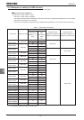
ۻ
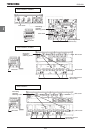
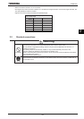
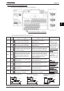
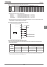
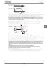
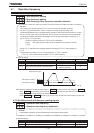
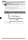
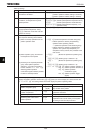
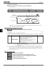
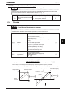
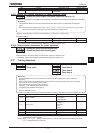
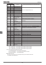
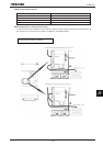
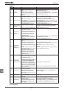
For coast stop
Open the connection between ST and CC
when stopping the motor in the state
described at left. The monitor on the inverter
at this time will display
QHH
.
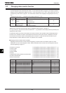
Motor
ON
OFF
ON
OFF
F-CC
ST-CC
Coast stop