


035-09651-001-A-0304
Unitary Products Group 9
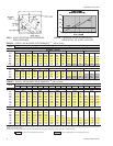
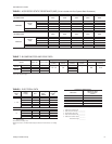
Model Accessory Static Resistance, IWG
BLOWER CFM 2400 2700 3000 3300 3600
F3EH090
Electric
Heat
10 KW 0.01 0.01 0.01 0.02 0.02
16 KW 0.01 0.02 0.02 0.03 0.04
26 KW 0.03 0.04 0.05 0.06 0.07
36 KW 0.05 0.07 0.08 0.10 0.11
Supply Air Plenum 0.03 0.03 0.04 0.05 0.06
Return Air Grille 0.02 0.03 0.04 0.05 0.06
BLOWER CFM 3200 3600 4000 4400 4800
F4EH120
Electric
Heat
10 KW 0.02 0.02 0.03 0.03 0.04
16 KW 0.03 0.04 0.05 0.06 0.07
26 KW 0.06 0.07 0.09 0.11 0.13
36 KW 0.09 0.11 0.14 0.17 0.20
Supply Air Plenum 0.05 0.06 0.07 0.08 0.10
Return Air Grille 0.05 0.06 0.07 0.08 0.10
TABLE 6 - ACCESSORY STATIC RESISTANCE (IWG)
(To be included with Duct System Static Resistance)
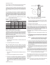
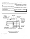
CONTROL WIRE SIZING
Wire Size
Maximum Total
Circuit Length
(Feet)
#19 Solid 130
#18 Solid 170
#18 Stranded 180
#16 Stranded 270
#14 Stranded 455
#12 Stranded 730
To determine the total circuit length, add the following distances:
1 - Outdoor Unit to Indoor Unit ___________
2 - Indoor Unit to Thermostat ____________
3 - Thermostat to Indoor Unit ____________
4 - Indoor Unit to Outdoor Unit ___________
5 - Outdoor Unit to Elec. Heater __________
Total Circuit Length __________
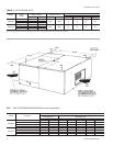
Model Motor HP* Blower RPM
Adjustable Motor Pulley Fixed Blower Pulley Belt
Pitch Dia.
(Inches)
Bore
(Inches)
Pitch Dia.
(Inches)
Bore
(Inches)
Designation
Pitch Lg.
(Inches)
60 Hz
F3EH090 1-1/2 655 - 880
2.8 - 3.8 7/8
7.5
1 A36 37.3
F4EH120 2 700 - 950 7.0
50 Hz
F3EH090 1-1/2 542 - 732 7.5
F4EH120 2 581 - 786 7.0
*These factory-mounted motors are wired for a 460V power supply. Refer to the wiring diagram inside the motor terminal box when reconnecting the motor leads for a
208 or 230 volt power supply.
TABLE 7 - BLOWER MOTOR AND DRIVE DATA
Blower
Motor
HP
Power
Supply
FLA
Max. Fuse
Size,
1
AMPS
Max. Wire
Length
2
(Ft.)
F3EH090
1-1/2
208-3-60 5.3 10 207
230-3-60 5.8 10 209
460-3-60 2.7 5 897
380-3-50 3.3 5 606
415-3-50 4.0 5 546
F4EH120
2
208-3-60 7.5 10 146
230-3-60 6.8 10 178
460-3-60 3.4 5 712
380-3-50 4.0 5 500
415-3-50 4.5 5 485
NOTE: Refer to Form 550.13-N10.1 for electrical data on units equipped with an electric
heat accessory.
1
Dual element, time delay fuses.
2
Based on three 60°C, 14 AWG, insulated copper conductors in steel conduit, a 3% voltage
drop.
TABLE 8 - ELECTRICAL DATA