


rate request for inspection by the carrier's agent should be
made in writing.
LIMITATIONS
These units must be installed in accordance with all national
andlocal safety codes. Ifno local codesapply, installationmust
conform with the appropriate national codes. Units are de
-
signedtomeet NationalSafetyCode Standards.Ifcomponents
are to be added to a unit to meet local codes, they are to be in
-
stalled at the dealer's and/or the customer's expense. See Ta
-
ble 2 for application limitations.
LOCATION
These indoor units are not designed for outdoor installation.
Theymust be locatedwithin thebuilding structure, eitherinside
or outside the conditioned space.
The units should be located as close to the outdoor units as
practical and positioned to minimize bends in the refrigerant
piping.
Unitsbeinginstalled verticallyor horizontallycan beset directly
on a floor or platform, or they can be supported by metal or
wooden beams.
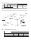
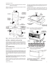
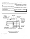
Units being installed horizontally can be suspended from
above. Four 3/8" weldnuts are providedin theunit frameto ac-
commodate hanger rods. Knockouts must be removed from
the unit panels to expose these weld nuts. Refer toFigure 1 for
their location and the individual load on each hanger rod.
WARNING: Be careful when attaching the hanger rods. Use a
washer witha back-up nut on each rod and tighten
down against the cabinet so they will not be al
-
lowed to turn or slip.
RIGGING AND HANDLING
Exercise care when moving the unit. Do not remove any pack
-
aging until the unit is near the place of installation.
The packaging consists of a bottom wooden skid that can be
liftedwith a forktruck from any direction, a cardboardcontainer
that covers the entire unit, and strapping that secures the card
-
board container to the bottom skid.
These units can be rigged with slings under the bottom skid.
CAUTION: Spreader bars should be used to prevent the
slings from crushing the unit panels and frame.
Before rigging any unit, determine its weight from Table1. Bef
-
orerigging a unitfor horizontalinstallation, determineits center
of gravity from Figure 1, and make sure that its weight will be
distributed equally.
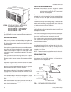
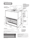
CLEARANCES
All units require certain minimum clearances for proper opera-
tion and service. Refer to Figure 12 for these clearances.
035-09651-001-A-0304
Unitary Products Group 3
INSTALLATION
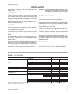
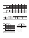
DESCRIPTION
UNIT MODEL
F3EH090 F4EH120
Coil
Rows Deep x Rows High 3 x 24 4 x 32
Finned Length - inches 45.5 45.5
Face Area - square feet 7.6 10.1
Tube (Copper) OD - inches 3/8 3/8
Fins (Aluminum) per inch 13 13
Centrifugal Blower (Forward Curve) Diameter x Width - inches 15 X 15 15 X 15
Blower Motor
1
Nominal Rating - HP 1-1/2 2
Filters (Throwaway)
Quantity Per Unit - 16" x 25" x 1" 4 4
Total Face Area - square feet 11.1 11.1
Refrigerant-22 (Lbs.)
2
Pumpdown Capacity 12.0 22.0
Unit Weight (lbs.)
Shipping 405 440
Operating 365 400
Accessory Operating Weights (Lbs.)
Electric Heaters
10 KW 63 63
16 KW 66 66
26 KW 71 71
36 KW 74 74
Supply Air Plenum 102 102
Base 60 60
Return Air Grille 15 15
1
All of these 1750 RPM motors have a solid base, a 56 frame, a 1.15 service factor, inherent protection & permanently lubricated ball bearings. Refer to page 6 for additional motor & drive data.
2
Refer to Form 035-15410-002 for system charge.
TABLE 1 - PHYSICAL DATA