


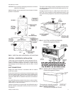

WARNING: Do not permit overhanging structures or shrubs to
obstruct air discharge.
Additional height may be required for snow clearance if winter
operation is expected.
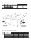
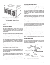
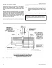
VERTICAL / HORIZONTAL INSTALLATION
These indoor units areshipped for vertical installation with ver
-
tical air discharge as shown in Figure 2(A) but may be con
-
verted for horizontal installation as shown in Figure 2(B) by
interchanging the solid bottom panel and the return air duct
flange.
DUCT CONNECTIONS
Design and install all ducts in accordance with all national
and/or local codes.
Ducts should be sized no smaller than the duct flanges on the
unit or the electric heater (ifused). Refer tothe unit dimensions
(Fig. 12) and the heater detail (Fig. 3) for these sizes. Refer to
Form035-16602-002 for installationinstructions on the electric
heater.
Use flexible fiberglass or plastic cloth collars or other nonflam
-
mable material at the unit duct connections to minimize the
transmission of noise and vibration.
Insulate all ductwork running through unconditioned areas to
prevent moisture condensation and to provide more economi
-
cal operation.
The return air ductflange is factory-mountedon the frontof the
unit, but it can be reversed with the solid bottom panel for hori
-
zontal applications.
A supply air plenum (Fig. 4), a base (Fig. 5) and a return air
grille (Fig. 6) are available as field-installed accessories, and
one of the following respective instructions will be packed with
each.
035-09651-001-A-0304
Unitary Products Group 5
FIG. 2 - VERTICAL AND HORIZONTAL APPLICATIONS
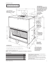
FIG. 3 - ELECTRIC HEATER ACCESSORY
(Vertical Arrangement Shown)
FIG. 4 - SUPPLY AIR PLENUM ACCESSORY
(Vertical Arrangement Shown)
FIG. 5 - BASE ACCESSORY
(For Vertical Arrangement Shown)