


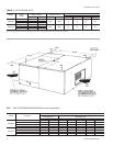
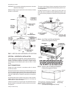
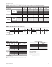

Form 035-16650-001 – Supply Air Plenum
Form 035-16621-001 – Return Air Grille
Form 035-16632-001 – Base
Thesupply airplenum andthe returnair grilleshould beused in
lieu of ductwork only when a free blow/freereturn application is
practical.
REFRIGERANT MAINS
Many service problems can be avoided by taking adequate
precautions to provide an internally clean and dry system and
by using procedures and materials that conform with estab-
lished standards.
Usehard drawncoppertubing whereno appreciableamount of
bending around pipes or other obstructions is necessary. Use
long radius ells wherever possible with one exception - small
radius ells for any traps in a vapor riser. If soft copper is used,
care should be taken to avoid sharp bends which may cause a
restriction.
Fiber glass insulation and a sealing material such as perma
-
gum should be packed around refrigerant lines where they
penetrate a wall to reduce vibration and to retain some flexibil
-
ity.
Support all refrigerant lines at minimum intervals with suitable
hangers, brackets or clamps.
Braze all copper to copper joints with Sil-Fos 5 or equivalent
brazing material. DO NOT USE SOFT SOLDER.
Never braze or solder the liquid and vapor lines together. The
completevapor lineshouldbe insulatedwith minimum1/2"AR
-
MAFLEX or equivalent.
If it is desirable to tape or wire these lines together for support
purposes, they must be completely insulated, one from the
other.
Refer to the installation instruction (Form 035-15410-002) for
the matching outdoor unit for piping limitations, line sizes, and
other design considerations.
INSTALLING REFRIGERANT MAINS
WARNING: Provisions for recovering refrigerant releases
must be available during all phases of installation,
leak testing and charging. Do NOT release refrig
-
erant into the atmosphere.
The units are evacuated and dehydrated at the factory and
shipped with a holding charge of an inert gas such as Nitrogen
or Helium. The vapor and liquid connections are sealed with
copper discs.
If the unit has already lost its holding charge, it should be leak
tested and the necessary repairs should be made. If the unit
has maintained its holding charge, you can assume that it has
no leaks and proceed with the installation.
The temperature required to make or break a brazed joint is
sufficientlyhightocauseoxidation ofthecopperunless aninert
atmosphere is provided.
Drilla small hole through the discsto prevent any internal pres
-
sure from blowingthem off andto allow the flow of dry nitrogen
through the connections when unbrazing the closures.
The liquid and vapor connections must be piped outside the
unit. Refer to the unit drawing for the locations and the dimen-
sions of these connections.
Before brazing the refrigerant lines to these connections, re-
move the short panel from the unit frame and slide the grom-
mets onto the refrigerant lines. After the brazed joints have
cooled, slide the grommets back into place and secure the
panel to the unit frame.
NOTE: Thesecoilscanonly bepipedfromoneside oftheunit.
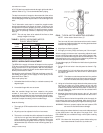
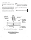
DRAIN CONNECTION
The drain line MUST be trapped because the coil is located on
the negative side of the supply air blower, and it must be pro
-
tected from freezing temperatures.
035-09651-001-A-0304
6 Unitary Products Group
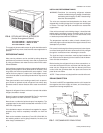
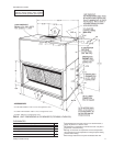
FIG. 6 - RETURN AIR GRILLE ACCESSORY
(Vertical Arrangement Shown)
FIG. 7 - RECOMMENDED DRAIN PIPING