


POWER AND CONTROL WIRING
Install electrical wiring in accordance with the latest National
Electrical Code (NFPA Standard No. 70) and/or local regula
-
tions. The unit should be grounded in accordance with these
codes.
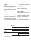
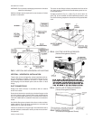
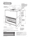
Route the power wires intothe unit through the 1-3/8” knockout
in the rear panel, and connect them to the terminals on blower
motor contactor 10M. Route the control wires into the unit
through the 7/8" hole in the rear panel, and connect them to the
terminals on block 4TB. Refer to the unit drawing in Fig. 12 for
the locations of these knockouts.
If the unit includes an electric heat accessory, route the power
wires into heater control box in lieu of the unit. Refer to electric
heat instruction Form 035-16602-002 for additional installation
information.
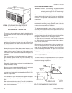
NOTE: Motors are wired for a 460V power supply.Refer to the
wiring diagram inside the motor terminal box when re
-
connecting motor leads for a 208 or 230 volt power
supply.
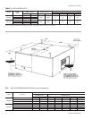
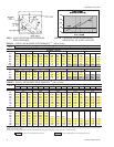
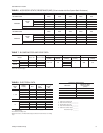
RefertoTable6tosizethedisconnect switch,thepower wiring,
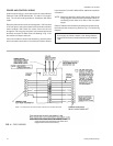
the fuses and the control wiring. Refer to Fig. 11 for field wiring
diagram.
035-09651-001-A-0304
10 Unitary Products Group
NOTE:
Refer to electric heat instruction 035-16602-002 for additional
power and control wire requirements if the indoor unit is
equipped with an electric heat accessory.
NOTE: For thermostat to be used on these units refer to form #036-13335-003.
FIG. 11 - FIELD WIRING
If the supply air blower rotates in the wrong direction,
reversetwoof themotor leadsatblower motorcontactor
10M.