


035-09651-001-A-0304
8 Unitary Products Group
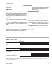
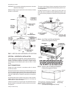
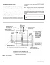
FIG. 9 - HOLE LOCATIONS FOR PRESSURE
DROP READINGS
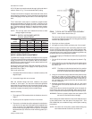
FIG. 10 - PRESSURE DROP ACROSS A DRY
INDOOR COIL VS. SUPPLY AIR CFM
RPM
CFM
ESP
2
BHP KW ESP
2
BHP KW ESP
2
BHP KW ESP
2
BHP KW ESP
2
BHP KW
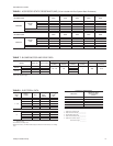
F3EH090 (60 Hz)
2400 2700 3000 3300 3600
600 0.30 0.62 0.79 0.21 0.70 0.76 0.09 0.78 0.89 ------
655 0.43 0.70 0.86 0.39 0.78 0.83 0.26 0.87 0.97 0.11 0.96 1.07 - - -
700 0.52 0.77 0.93 0.48 0.85 0.90 0.40 0.95 1.06 0.28 1.06 1.16 0.14 1.17 1.26
800 0.82 0.97 1.10 0.81 1.06 1.07 0.74 1.18 1.27 0.63 1.30 1.38 0.51 1.42 1.49
880 1.10 1.11 1.24 1.09 1.24 1.21 1.02 1.37 1.45 0.91 1.50 1.55 0.78 1.64 1.70
900 1.15 1.15 1.27 1.14 1.28 1.24 1.07 1.42 1.49 0.97 1.55 1.60 0.87 1.70 1.74
1000 1.49 1.35 1.46 1.47 1.48 1.43 1.42 1.63 1.65 1.35 1.81 1.82 1.27 2.02 2.02
F4EH120 (60 Hz)
3200 3600 4000 4400 4800
700 0.30 1.01 1.17 0.15 1.17 1.27 ---------
800 0.66 1.25 1.38 0.52 1.42 1.51 0.31 1.60 1.64 0.08 1.80 1.78 - - -
900 0.99 1.48 1.60 0.87 1.70 1.77 0.69 1.92 1.93 0.47 2.18 2.09 0.19 2.45 2.23
950 1.20 1.61 1.71 1.08 1.86 1.90 0.90 2.12 2.07 0.72 2.39 2.23 0.41 2.67 2.42
1000 1.37 1.75 1.83 1.27 2.02 2.02 1.11 2.30 2.20 0.92 2.60 2.39 0.63 2.90 2.59
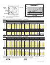
TABLE 4 - SUPPLY AIR BLOWER PERFORMANCE
1,3
(60 Hz Units)
RPM
CFM
ESP
2
BHP KW ESP
2
BHP KW ESP
2
BHP KW ESP
2
BHP KW ESP
2
BHP KW
F3EH090 (50 Hz)
2000 2250 2500 2750 3000
500 0.22 0.43 0.41 0.16 0.48 0.46 0.08 0.53 0.50 ------
542 0.30 0.47 0.45 0.25 0.53 0.50 0.18 0.58 0.55 0.10 0.63 0.60 - - -
550 0.32 0.48 0.46 0.27 0.54 0.51 0.20 0.59 0.56 0.12 0.64 0.61 0.01 0.70 0.66
600 0.42 0.54 0.51 0.38 0.60 0.57 0.32 0.66 0.62 0.23 0.72 0.68 0.13 0.78 0.73
650 0.54 0.60 0.57 0.50 0.66 0.62 0.45 0.73 0.68 0.37 0.79 0.74 0.28 0.85 0.80
700 0.67 0.67 0.63 0.63 0.73 0.69 0.58 0.80 0.75 0.52 0.87 0.82 0.43 0.95 0.89
732 0.77 0.71 0.67 0.73 0.77 0.72 0.68 0.84 0.79 0.62 0.93 0.87 0.54 1.02 0.96
750 0.83 0.74 0.69 0.79 0.80 0.75 0.73 0.87 0.82 0.68 0.97 0.91 0.60 1.07 1.00
F4EH120 (50 Hz)
2800 3150 3500 3850 4200
550 0.14 0.65 0.60 ------------
581 0.21 0.70 0.64 0.05 0.77 0.70 ---------
600 0.26 0.73 0.67 0.10 0.80 0.73 ---------
650 0.40 0.81 0.74 0.25 0.89 0.82 0.11 0.98 0.91 ------
700 0.54 0.90 0.83 0.41 1.00 0.93 0.27 1.11 1.03 0.10 1.25 1.16 - 1.40 1.29
750 0.70 0.99 0.92 0.58 1.12 1.04 0.45 1.25 1.16 0.29 1.40 1.29 0.10 1.55 1.43
786 0.81 1.06 0.98 0.71 1.21 1.13 0.59 1.36 1.26 0.43 1.51 1.39 0.24 1.66 1.54
800 0.86 1.09 1.01 0.76 1.25 1.16 0.64 1.41 1.30 0.49 1.55 1.43 0.30 1.71 1.58
1
Unit resistance is based on a wet indoor coil and clean filters.
2
Available static pressure in IWG to overcome the resistance of the duct system and any accessories added to the unit. Refer to the Tables 6 & 7 for the resistance of these accessories and for
additional motor and drive data .
3
Motors can be selected to operate into the service factor because they are located in the moving air stream, upstream of any heating device.
TABLE 5 - SUPPLY AIR BLOWER PERFORMANCE
1,3
(50 Hz Units)
RPM range for the standard drive components.
Exceeds the BHP limitations of the standard blower motor.