


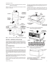

A7/8" OD drain connection extends through right hand side of
cabinet. Refer to Fig. 7 for recommended drain piping.
The drain connection is located on the same side of the unit as
therefrigerant connections.The lineshould beinsulated where
moisturedrippagewillbe objectionableorcause damagetothe
area.
The 3" dimension must equal or exceed the negative static
pressure developed by the supply air blower. If it does not, the
condensate will not drain properly and may overflow the drain
pan. The trap must be at least 2-1/2" deep to maintain a water
seal under all operating conditions, especially during blower
start-up.
NOTE: The unit may have to be raised off the floor to allow
enough height for the trap.
SUPPLY AIR BLOWER ADJUSTMENT
The RPM of the supply air blower will depend on the required
CFM,theunit accessoriesandthe staticresistancesofboththe
supply and the return air duct systems. With this information,
the RPM for the supply air blower can be determined from the
blower performance in Table 4.
Knowing the required blower RPM and the blower motor HP,
the setting (turns open) for the supply air motor pulley can be
determined from Table 3.
Each motor pulley has:
1. A threaded barrel with two flats (or notched recesses) 180
degrees apart.
2. A movable flange with one set screw.
After the movable flange has been rotated to the proper
number of “turns open”, the set screw should be tightened
againsttheflat onthe barreltolock themovable flangeinplace.
If the pulley includes alocking collar, the lockingcollar must be
loosened to adjust the setting of the movable flange.
Note the following:
1. The supply air CFM must be within the limitations shown in
Table 2.
2. All pulleys can be adjusted in half turn increments.
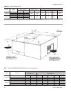
3. The tension on the belt should be adjusted for a deflection
of 3/16 of an inch per foot of belt span with an applied force
of 2 to 3 pounds. This adjustment is made by moving the
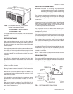
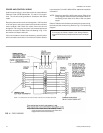
blower motormounting plate. Refer to Figure 8.Turningthe
adjustment bolt (B) moves the motor mounting plate up or
down.
NOTE: Never loosen the two nuts (C).
Two hex nuts (A) have to be loosened to move the mount
-
ingplate and retightened after themounting plate has been
moved to the proper position.
4. All pulleys are factory aligned.
5. All supply air motor pulleys are factory set 3 “turns open”.
After the supply air blower motor is operating, adjust the resis
-
tances in both the supply and the return duct systems to bal
-
ance theair distribution throughout the conditioned space.The
job specifications may require that this balancing be done by
someone other than the equipment installer.
To checkthe supplyair CFMafter theinitial balancinghas been
completed:
1. Drill two 5/16 inch holes in the side panel as shown in Fig-
ure 9.
2. Insert at least 6" of 1/4 inch tubing into each of these holes
for sufficient penetration into the air flow on both sides of
the indoor coil.
NOTE: Thetubes must be inserted and held in a position
perpendicular to the air flow so that velocity pres
-
sure will not affect the static pressure readings.
3. Usingan inclined manometer,determine the pressuredrop
across a dry indoor coil. Since moisture on the coil may
vary greatly,measuring the pressure drop across awet coil
under field conditions wouldbe inaccurate.Toassure a dry
coil, the heat pump system should be de-activated while
the test is being run.
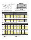
4. Knowing the pressure drop across a dry coil, the actual
CFM through the unit can be determined from the curve in
Figure 10.
If the CFMis aboveor below the specified value,the supplyair
motor pulley may have to be readjusted. After one hour of op
-
eration,checkthebeltand pulleysfortightnessand alignment.
WARNING: Failure to properly adjust the total system CFM
can result in extensive blower damage.
After readings have beenobtained, remove thetubes andseal
up the drilled holes in the side panel. Dot plugs (5/16" - P/N
029-13880-000) are available through normal parts ordering
procedures.
NOTE: Shut down the heat pump system before taking any
test measurements to assure a dry indoor coil.
035-09651-001-A-0304
Unitary Products Group 7
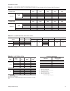
FIG. 8 - TYPICAL MOTOR MOUNTING ASSEMBLY
TURNS
OPEN*
MODEL
F3EH090
60 Hz
F3EH090
50 Hz
F4EH120
60 Hz
F4EH120
50 Hz
5 655 RPM 542 RPM 700RPM 581 RPM
4 760 580 750 622
3 745 618 800 663
2 790 656 850 704
1 835 694 900 745
0 880 732 950 786
*Pulleys can be adjusted in half-turn increments.
TABLE 3 - SUPPLY AIR BLOWER MOTOR
PULLEY ADJUSTMENT