


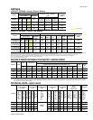
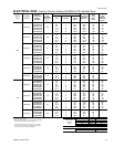
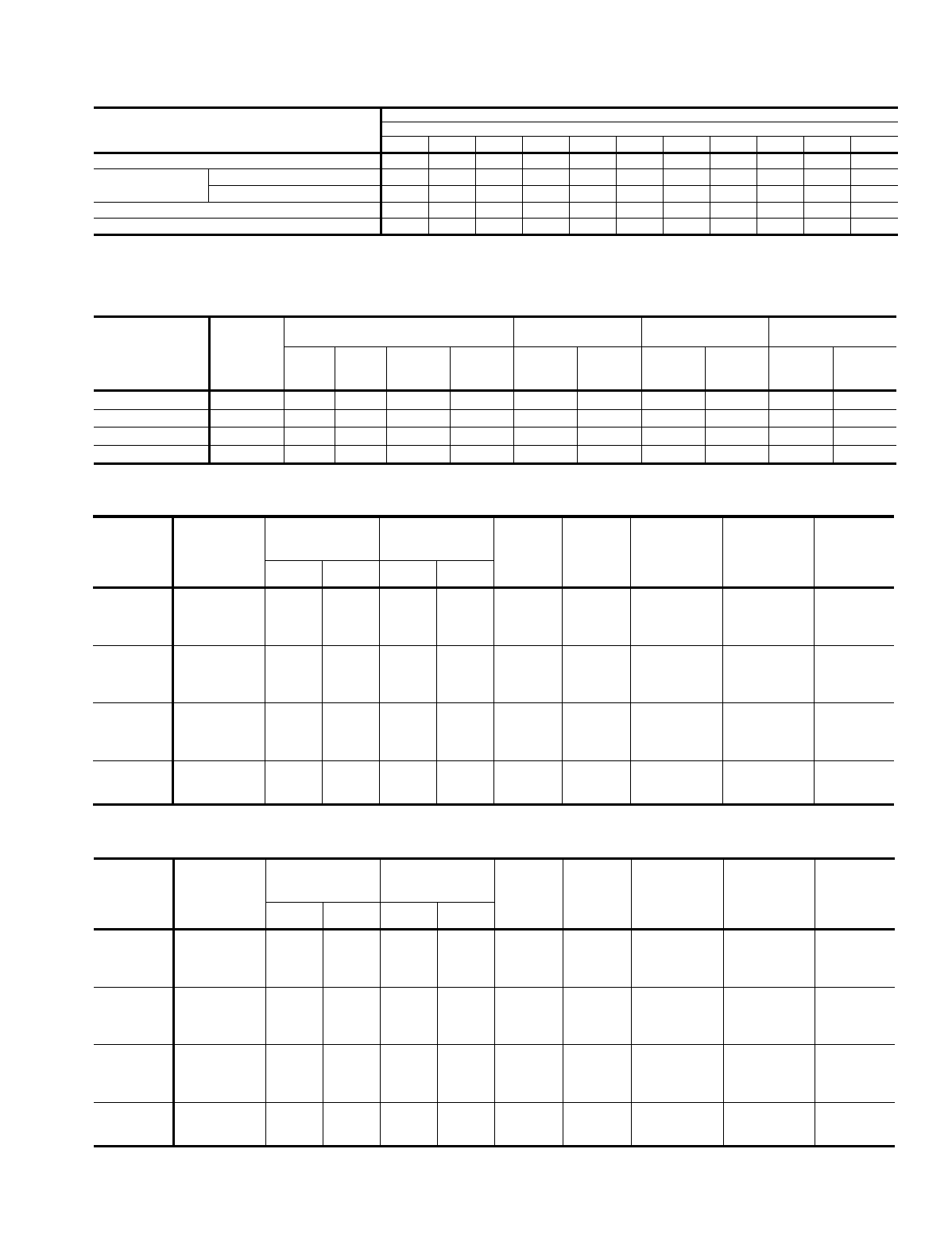
MODEL
DCE
DCG
POWER
SUPPLY
VOLTAGE
LIMITATIONS
(SEE NOTE 1)
SCROLL
COMPRESSOR
COND.
FAN
MOTOR,
FLA
SUPPLY
AIR
BLOWER
MOTOR,
FLA
MINIMUM
CIRCUIT
AMPACITY
MAX.
FUSE
SIZE,
(SEE NOTE 2)
AMPS
MAX.
HACR
BREAKER
SIZE,
AMPS
MIN. MAX. RLA LRA
036
208/230-1-60
208/230-3-60
460-3-60
575-3-60
187
187
414
518
253
253
504
630
18.0
11.4
6.2
5.0
105.0
90.0
45.0
36.0
1.3
1.3
0.8
0.8
4.4
4.4
2.2
2.2
28.2
20.0
10.8
9.3
45
30
15
15
45
30
15
-
048
208/230-1-60
208/230-3-60
460-3-60
575-3-60
187
187
414
518
253
253
504
630
24.4
14.1
7.1
5.6
140.0
105.0
55.0
44.0
1.3
1.3
0.8
0.8
5.0
5.0
2.2
2.2
36.8
23.9
11.9
10.1
60
35
15
15
60
35
15
-
060
208/230-1-60
208/230-3-60
460-3-60
575-3-60
187
187
414
518
253
253
504
630
28.9
16.0
8.0
6.4
165.0
125.0
67.0
50.0
1.3
1.3
0.8
0.8
6.6
6.6
3.3
3.3
44.0
27.9
14.1
12.1
70
40
20
15
70
40
20
-
072
208/230-3-60
460-3-60
575-3-60
187
414
518
253
504
630
20.3
10.2
8.2
146.0
73.0
58.4
1.3
0.8
0.8
6.8
3.6
3.6
33.5
17.2
14.7
50
25
20
50
25
-
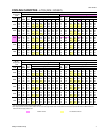
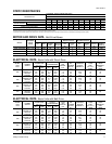
NOTES: 1. Utilization Range “A” in accordance with ARI Standard 110. 2. Dual element, time delay type.
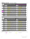
MODEL
DCE
DCG
POWER
SUPPLY
VOLTAGE
LIMITATIONS
(SEE NOTE 1)
SCROLL
COMPRESSOR
COND.
FAN
MOTOR,
FLA
SUPPLY
AIR
BLOWER
MOTOR,
FLA
MINIMUM
CIRCUIT
AMPACITY
MAX.
FUSE
SIZE,
(SEE NOTE 2)
AMPS
MAX.
HACR
BREAKER
SIZE,
AMPS
MIN. MAX. RLA LRA
036
208/230-1-60
208/230-3-60
460-3-60
575-3-60
187
187
414
518
253
253
504
630
18.0
11.4
6.2
5.0
105.0
90.0
45.0
36.0
1.3
1.3
0.8
0.8
5.3
5.3
3.1
3.1
29.1
20.9
11.7
10.2
45
30
15
15
45
30
15
-
048
208/230-1-60
208/230-3-60
460-3-60
575-3-60
187
187
414
518
253
253
504
630
24.4
14.1
7.1
5.6
140.0
105.0
55.0
44.0
1.3
1.3
0.8
0.8
8.6
5.2
2.6
2.0
40.4
24.1
12.3
9.9
60
35
15
15
60
35
15
-
060
208/230-1-60
208/230-3-60
460-3-60
575-3-60
187
187
414
518
253
253
504
630
28.9
16.0
8.0
6.4
165.0
125.0
67.0
50.0
1.3
1.3
0.8
0.8
8.6
6.0
3.0
2.4
46.0
27.3
13.8
11.2
70
40
20
15
70
40
20
-
072
208/230-3-60
460-3-60
575-3-60
187
414
518
253
504
630
20.3
10.2
8.2
146.0
73.0
58.4
1.3
0.8
0.8
7.3
3.7
2.8
34.0
17.3
13.9
50
25
20
50
25
-
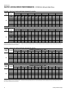
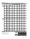
NOTES: 1. Rated in accordance with ARI Standard 110, utilization range "A". 2. Dual element, time delay type.
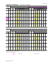
ELECTRICAL DATA
-
Basic Units with Belt-Drive
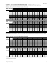
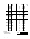
EXTERNAL STATIC PRESSURE DROP
DESCRIPTION
RESISTANCE, IWG
CFM
1000 1200 1400 1600 1800 2000 2200 2400 2600 2800 3000
Economizer
1, 3
0.07 0.08 0.09 0.11 0.13 0.15 0.17 0.20 0.23 0.26 0.30
Electric Heaters
1
5 - 15 KW 0.04 0.05 0.06 0.07 0.08 0.10 0.12 0.14 0.16 0.19 0.22
20 - 30 KW 0.06 0.07 0.08 0.09 0.11 0.13 0.15 0.17 0.20 0.23 0.26
Bottom Duct Connections
1
0.06 0.07 0.08 0.09 0.10 0.11 0.12 0.14 0.16 0.19 0.22
Cooling Only
2
0.08 0.10 0.12 0.14 0.16 0.18 0.20 0.23 0.26 0.29 0.32
1
Deduct these resistance values from the available external static pressure shown in the respective Blower Performance Table.
2
Add these resistance values to the available static resistance in the respective Blower Performance Table.
3
The pressure thru the economizer is greater for 100% outdoor air than for 100% return air. If the resistance of the return air duct system is less than 0.25 IWG, the unit will deliver less CFM during full economizer operation.
STATIC RESISTANCES
MOTOR AND DRIVE DATA
-
Belt-Drive Blower
MODEL
BLOWER
RANGE
(RPM)
MOTOR*
ADJUSTABLE
MOTOR PULLEY
FIXED
BLOWER PULLEY
BELT
HP RPM
FRAME
SIZE
SERVICE
FACTOR
PITCH
DIA.
(in.)
BORE
(in.)
PITCH
DIA.
(in.)
BORE
(in.)
PITCH
LENGTH
(in.)
DESIG-
NATION
DCE / DCG 036 790 - 1120 1
1
⁄
2
1725 56 1.15 2.4 - 3.4
7
⁄
8
5.7 1 37.3 A36
DCE / DCG 048 790 - 1120
1
1
⁄
2
1725 56 1.15 2.4 - 3.4
7
⁄
8
5.7 1 37.3 A36
DCE / DCG 060 850 - 1220 1
1
⁄
2
1725 56 1.15 2.4 - 3.4
7
⁄
8
5.2 1 37.3 A36
DCE / DCG 072 900 - 1250
1
1
⁄
2
1725 56 1.15 2.8 - 3.8
7
⁄
8
5.2 1 37.3 A36
*
All motors have solid bases and are inherently protected. These motors can be selected to operate into their service factor because they are located in the moving air, upstream of any heating device.
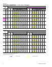
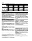
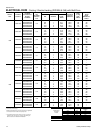
ELECTRICAL DATA
-
Basic Units with Direct-Drive
530.18-TG1Y
Unitary Products Group 11