


19
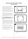
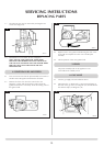
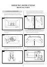
6.3 Undo the single screw that secures the left hand side of the
control cover (see Diagram 10).
10
AR0915
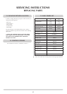
6.4 To release the right hand side of the control cover insert the
narrow blade screwdriver into the slot shown in Diagram
11. Lever it gently and pull from the right hand side at the
same time. The cover will now come off. There is a small
cylindrical metal spacer inside the cover, this must be kept
and replaced on the fixing screw during re-assembly.
11
AR0915
6.5 Disconnect the ignition lead from the gas valve.
6.6 Undo the two bolts (see Diagram 9, C) securing the gas
valve to the appliance and remove the valve.
6.7 Replace in reverse order.
6.8 Check all joints for gas leaks and check operation of the
thermocouple and ignition lead.
7. MAGNETIC SAFETY VALVE
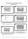
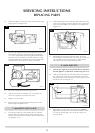
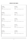
7.1 Turn the gas supply off at the isolation device. Undo the
thermocouple connection from the back of the gas valve,
pull the sensor leads clear and remove the interrupter block
(see Diagram 12, A).
7.2 Undo the magnetic valve-retaining nut from the back of the
control valve, gently tap out the magnetic valve and replace
with a new unit. Replace the retaining nut and tighten (see
Diagram 12).
12
AR0915
A
7.3 Reassemble the interrupter block and leads. Secure the
thermocouple connection in the rear of the gas control. (Do
not overtighten). Turn the gas supply on and check the
entire pipe work and valve joints for any leaks.
8. MAIN INJECTOR
8.1 Turn the gas supply off at the isolation device and ensure
that the appliance is cold before commencing work on it.
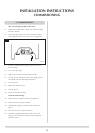
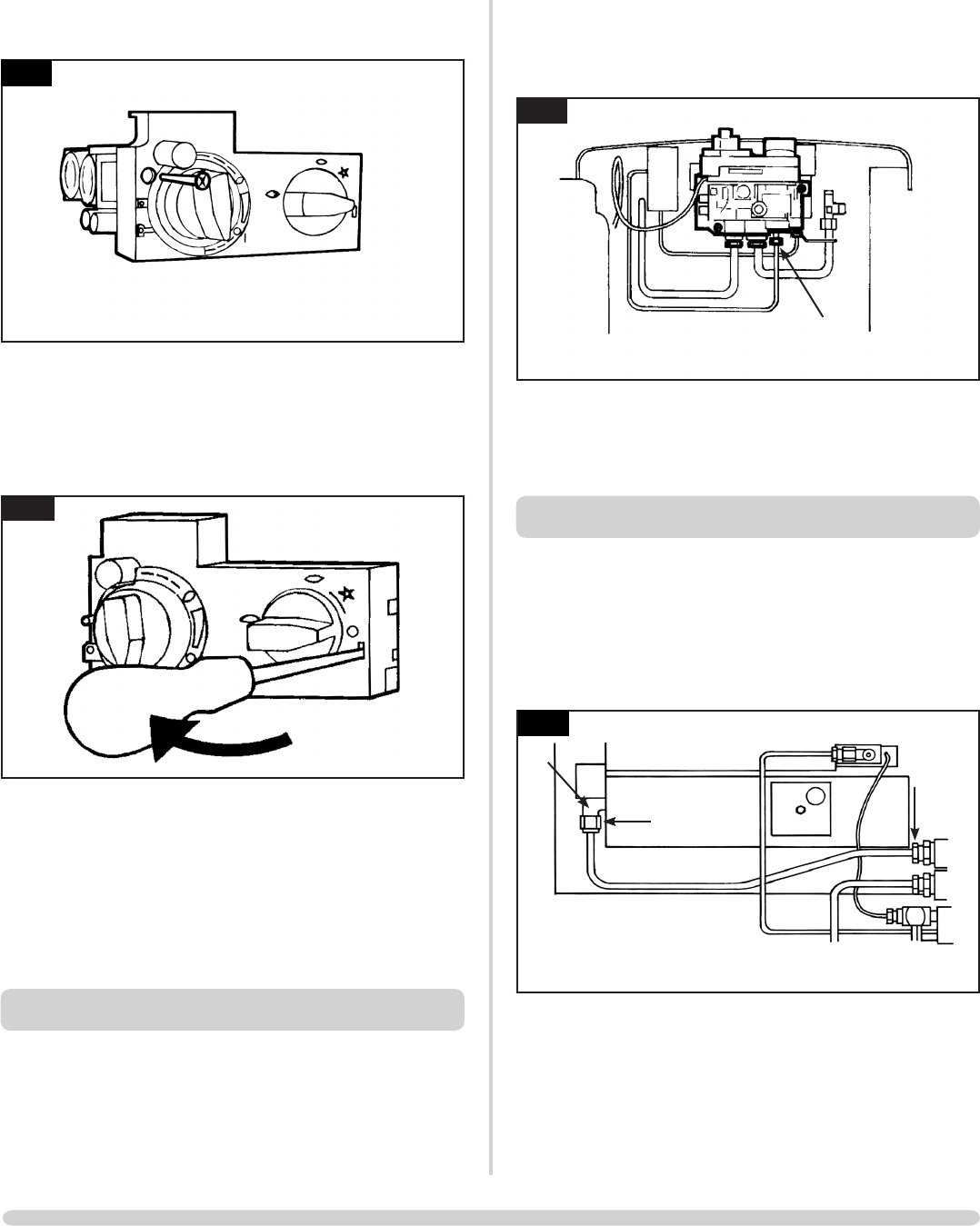
8.2 Undo the compression nut from the injector (A) and loosen
the compression nut (B) in the gas valve body. Disconnect
the pipe from the injector and unscrew the injector (C) from
the burner unit (see Diagram 13).
AR1441
C
B
A
13
8.3 Reassemble in reverse order. The injector must NOT be
tightened into the burner but be allowed to float to enable
it to line up with the pipe. Turn on the gas supply and
check for leaks.
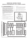
SERVICING INSTRUCTIONS
REPLACING PARTS