


Table of Contents
Installation . . . . . . . . . . . . . . . . . . . . . . . . . . . . . . . . . . . . . . . . . . . . . 4
Battery Location. . . . . . . . . . . . . . . . . . . . . . . . . . . . . . . . . . . . . . . . . . 4
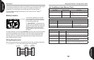
Wiring Requirements . . . . . . . . . . . . . . . . . . . . . . . . . . . . . . . . . . . . . . 4
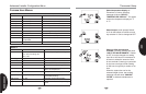
Quick Installation Steps . . . . . . . . . . . . . . . . . . . . . . . . . . . . . . . . . . . . 5
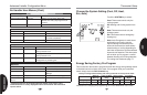
Installing Thermostat . . . . . . . . . . . . . . . . . . . . . . . . . . . . . . . . . . . . . . 5
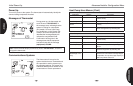
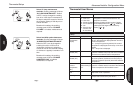
Initial Power Up. . . . . . . . . . . . . . . . . . . . . . . . . . . . . . . . . . . . . . . . 6
Thermostat Setup . . . . . . . . . . . . . . . . . . . . . . . . . . . . . . . . . . . . . 8
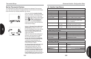
Set Current Time and Day . . . . . . . . . . . . . . . . . . . . . . . . . . . . . . . . . . 8
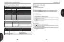
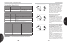
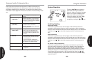
Choose the System Setting . . . . . . . . . . . . . . . . . . . . . . . . . . . . . . . . . 9
Energy Saving Factory Program . . . . . . . . . . . . . . . . . . . . . . . . . . . . . 9
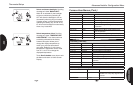
Set Up Thermostat Options . . . . . . . . . . . . . . . . . . . . . . . . . . . . . . . . . 10
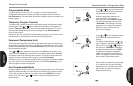
Using the Thermostat . . . . . . . . . . . . . . . . . . . . . . . . . . . . . . . . . 15
Advanced Installer Confi guration
Menu/Service Information
. . . . . . . . . . . . . . . . . . . . . . . . 19
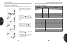
Entering and Navigating the Advanced Installer
Confi guration Menu/Service Information . . . . . . . . . . . . . . . . . . . . 19
Equipment User Menus . . . . . . . . . . . . . . . . . . . . . . . . . . . . . . . . . . . . 20
Thermostat User Menus . . . . . . . . . . . . . . . . . . . . . . . . . . . . . . . . . . . 23
Furnace User Menus . . . . . . . . . . . . . . . . . . . . . . . . . . . . . . . . . . . . . . 24
Air Handler User Menus. . . . . . . . . . . . . . . . . . . . . . . . . . . . . . . . . . . . 27
Heat Pump User Menus. . . . . . . . . . . . . . . . . . . . . . . . . . . . . . . . . . . . 29
Air Conditioner User Menus. . . . . . . . . . . . . . . . . . . . . . . . . . . . . . . . . 32
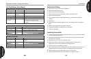
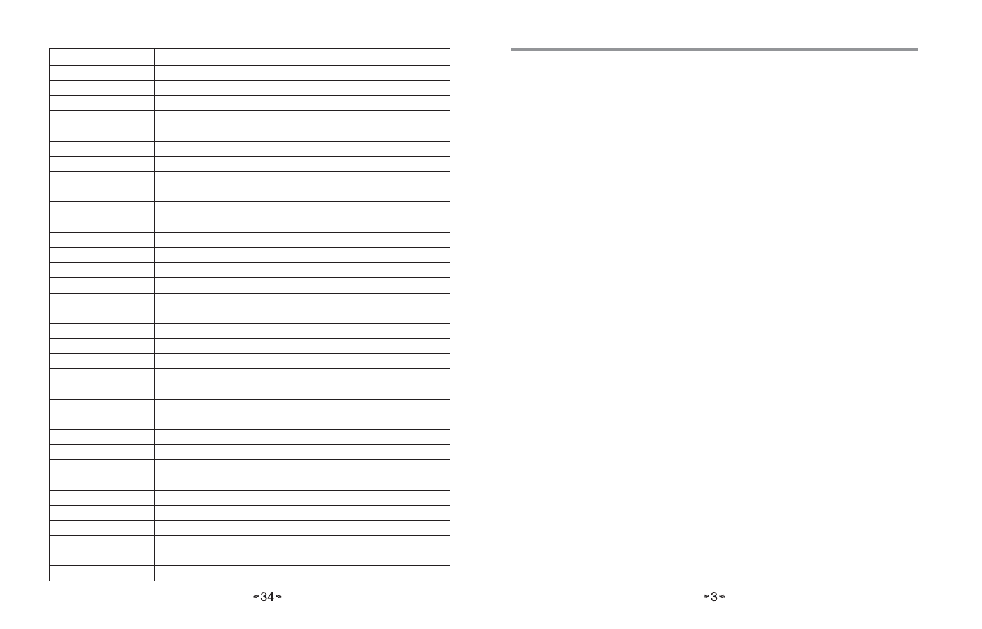
System Fault Codes
Display code Diagnostic Description
1 Long Run Time
2 System Pressure Trip
3 Short Cycling
4 (L4) Locked Rotor
5 (L5) Open Circuit
6 (L6) Open Start Circuit
7 (L7) Open Run Circuit
9 Low Secondary Voltage
11 Failed ignition
12 Low fl ame sense current
13 Flame lost after established
14 Flame present with gas valve off
21 (L21) Low Pressure Switch Trip
22 Main limit switch open.
23 Auxiliary limit switch open
26 Line Neutral Reversed
27 Check Line Voltage
28 High Line Voltage
29 (L29) High Pressure Switch Trip
30 Fuse Open
33 MRLC Open
44 Low pressure switch closed, inducer off
45 Low pressure switch open, inducer on high speed
46 Low pressure switch open, inducer on low speed
55 High pressure switch closed, inducer off
57 High pressure switch open, inducer on high speed
60 Blower Fault Run
61 Blower Fault No Run
66 RPM out of range (over 1200 RPM)
68 No Blower Communication
77 Servo circuit open
78 Servo control fault
79 No Gas Valve Feedback
80 Low Airfl ow