


15
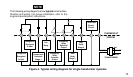
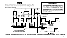
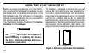
Figure 6. Typical wiring diagram for two transformer systems with safety circuits in BOTH systems
TWO COMMONS MUST
BE JUMPERED TOGETHER!
C
R
G
B
O
THERMOSTAT
SYSTEM
Y1
W2E1
E2
HEAT PUMP SYSTEM AUXILIARY
HEATING SYSTEM
W1
Changeover
Energized
In Cool
Changeover
Energized
In Heat
Fan
Relay
Compressor
Contactor
Stage 1
Emergency
Relay
Switched
Output
Thermostat
Control
Circuit
Emergency
Relay
Constant
Output
Heat
Relay
Stage 1
Heat
Relay
Stage 2
24 VAC
120 VAC
Hot
Neutral
HEAT PUMP
TRANSFORMER
24 VAC
120 VAC
Hot
Neutral
AUXILIARY
HEATING
TRANSFORMER
24 VAC
Accessory
Relay N.O.
Contact
Limit or
Safety
Switches
Limit or
Safety
Switches
Limit or
Safety
Switches
Limit or
Safety
Switches
NOTE
Relay contacts shown are thermostatically operated. The
accessory relay scheme is required when safety circuits
exist in both systems.
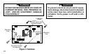
Polarity must be observed. If the HOT
side of the second transformer is
jumpered to the COMMON side of the
first transformer a short will be made.
Damage to equipment will occur when
power is restored.
CAUTION
!