


13
C R
G
B
O
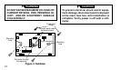
Changeover
Energized
In Heat
Changeover
Energized
In Cool
Compressor
Contactor
Stage 1
Fan
Relay
Heat
Relay
Stage 1
Heat
Relay
Stage 2
Thermostat
Control
Circuit
24 VAC 120 VAC
Hot
Neutral
THERMOSTAT
SYSTEM
Y1 W1
W2
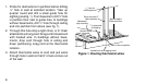
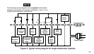
Figure 4. Typical wiring diagram for single transformer systems
E1
Emergency
Relay
Constant
Output
E2
Emergency
Relay
Switched
Output
TRANSFORMER
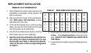
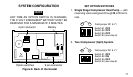
The following wiring diagrams show typical terminal iden-
tification and wiring. For proper installation, refer to the
original manufacturers' instructions.
NOTE