


GOLD
CGi-4E Gas-Fired Water Boiler — Boiler Manual
48
Part Number 550-110-711/1108
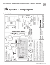
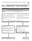
Troubleshooting — general11a
Air pressure switch
Make sure boiler water temperature is
100 °F or cooler before starting proce-
dure to obtain appropriate readings.
The boiler will not operate correctly un-
less pressure switch hoses are correctly
located. The red hose connects from
the right side (negative) hose barb to
the flue collector. The white hose con-
nects from the left side (positive) hose
barb of the switch to the connector box
(between flue collector and inducer) as
shown in Figure 36, page 49.
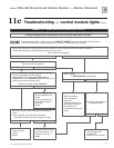
Check pressure switch setting
1. SeeFigure 36, page 49, and Table 9.
2. Remove both air pressure switch hoses from air pressure
switch.
3. Install tees and tubing as shown in
Figure 36, page 49, to
inclined manometer.
4. Turn off gas valve and set thermostat to call for heat. Inducer
will run but burners will not ignite.
5. Checkfor24VACbetweenbothairpressureswitchtermi-
nals.
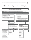
Troubleshooting air pressure reading
1. If manometer reading is lower than the setpoint of the switch
(see
Table 9) — check for possible causes:
• blockageinhoses
• obstructionininducerhousingoutlet
• looseinducerwheelonmotorshaft
• inducermotornotinproperrpm
• inducerbackplatenotsealedproperly
• blockageinblockassembly
• blockageinuepipeortermination
• incorrectpressureswitch
6. If manometer reading is above the setpoint of the switch (see
Table 9),butthereisnot24VACbetweenbothairpressure
switch terminals — replace air pressure switch.
Return to normal operation
When pressure reading is correct and air pressure switch is oper-
ating properly — remove tees and reinstall hoses to air pressure
switch.
Table 9 Pressure switch setpoint (for elevations
above 2,000 ft, contact your local Weil-
McLain sales office for details.)
Boiler model number Inches W.C.
CGi-4E
1.36
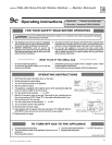
Label all wires prior to disconnection when
servicing controls. Wiring errors can cause
improper and dangerous operation.
Neverjumper(bypass)rolloutthermalfuseele-
ment or any other device except for momentary
testing as outlined in Troubleshooting Charts.
Severepersonalinjury, deathorsubstantial
property damage can result.
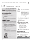
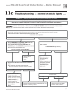
Before troubleshooting:
1. Have the following items:
a. Voltmeter that can check 120 VAC and 24 VAC.
b. Microammeter with a minimum scale range of 0-25.
c. Continuity checker.
d. U-tube manometer.
2. Check for 120 VAC (minimum 102 VAC to maximum 132 VAC) to
boi ler.
3. Make sure thermostat is calling for heat and contacts (including appro-
priate zone controls) are closed. Check for 24 VAC between thermostat
wire nuts and ground.
Check the following:
1. Wire connectors to control module are securely plugged in at module
and originating control.
2. Air pressure switch hoses are properly and securely plugged in and are
not damaged.
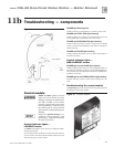
3. Verify gas supply pressure:
a. With boiler OFF — 13” w.c. maximum natural or propane gas
pressure upstream of gas valve.
b. With boiler ON — Upstream: 5” w.c. minimum natural gas pres-
sure or 11” w.c. propane gas pressure upstream of gas valve.
4. Verify gas manifold pressure (downstream of gas valve):
a. Natural gas:
Manifold pressure, high fire: 3.50” w.c.
Manifold pressure, low fire: 0.90” w.c. while in low fire at start-up
(60 seconds)
b. Propane gas:
Manifold pressure, high fire: 10.0” w.c.
Manifold pressure, low fire: 3.50” w.c. while in low fire at start-up
(60 seconds)
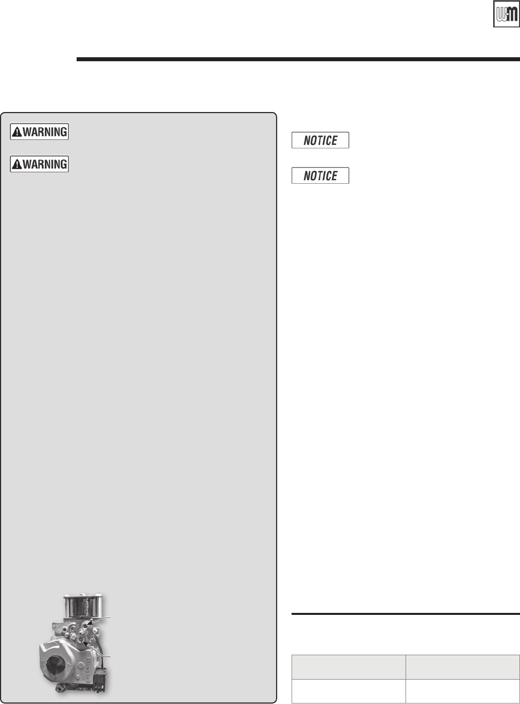
c. If necessary, adjust gas pressure on the gas valve as shown below.
After adjustments, refer to page 35 to check the flame.
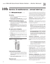
High-re gas pressure adjustment
Low-re gas pressure adjustment
Honeywell VR8204Q two-stage gas valve