


GOLD
CGi-4E Gas-Fired Water Boiler — Boiler Manual
20
Part Number 550-110-711/1108
Water piping — general information4a
General piping information
IfinstallationistocomplywithASMEorCanadianrequirements,anad-
ditional high temperature limit is needed. Install control in supply piping
betweenboilerandisolationvalve.Setsecondcontroltominimum20°F
abovesetpointofrstcontrol.Maximumallowablesetpointis240°F.See
Section9b for wiring.
A low water cutoff device is required when boiler is installed above ra-
diation level or by certain state or local codes or insurance companies. Use
low water cutoff designed for water installations. Electrode probe-type is
recommended. Purchase and install in tee in supply piping above boiler.
Use backflow check valve in cold water supply as required by local
codes.
Pressure/temperature gauge
Install pressure/temperature gauge in tee on supply piping (as shown in
drawing on page 3).
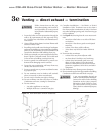
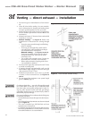
Relief valve
Installreliefvalveverticallyin¾”tappingonsideofboiler.SeeFigure 16
or 17, page 21, and the tag attached to the relief valve for manufacturer’s
instructions.
Table 6 Water pipe size (based on 20°F rise)
Boiler
model number
To
system
From
system
CGi-4E
1” 1”
Note: The boiler supply and return connections, the return/
drain tee and the supply/gauge tee supplied with
the boiler are 1¼” NPT. One of the circulator flanges
supplied with the boiler is 1¼”. The other circulator
flange is the size of the recommended system piping
shown above.
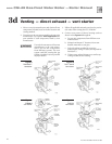
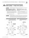
Circulator
The circulator is shipped loose (wiring pre-attached to
boiler) to allow you to locate it either in the return or
supplypiping,asdesired.Seepage3foratypicalinstal-
lation. Pipe the expansion tank to the suction side of the
circulator whenever possible. Install an air separator in
thesupplypiping.Connecttheexpansiontanktotheair
separator only if the separator is on the suction side of
the circulator. Always install the system fill connection
at the same point as the expansion tank connection to
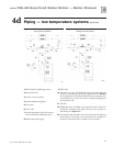
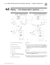
the system. Figures 16 and 17 show typical near-boiler
piping connections.
System water piping
SeeFigure 16 (diaphragm-type or bladder-type expan-
sion tank) or Figure 17 (closed-type expansion tank)
and Table 6, for near-boiler and single-zone systems
designed for return water at least 130°F.
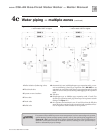
Seepages22-23tocompletemultiple-zonepipingor
pages 24-29 to complete piping for radiant heating
systems or converted gravity systems (large-volume
systems originally designed for circulation by natural
convection rather than a pump).Seepage29forboilers
used with refrigeration systems.
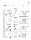
Chillers or air handling units:
Install boiler such that —
• Chilledmedium,ifused,ispipedinparallelwith
heating boiler. Use appropriate valves to prevent
chilled medium from entering boiler.Consult
I=B=RInstallationandPipingGuides.
• Ifboiler is connectedto heating coils locatedin
air handling units where they can be exposed to
refrigerated air, use flow control valves or other au-
tomatic means to prevent gravity circulation during
coolingcycle.Circulationofcoldwaterthroughthe
boiler could result in damage to the heat exchanger,
causing possible severe personal injury, death or
substantial property damage.
To avoid water damage or scalding due to relief valve
operation:
• Dischargelinemustbeconnectedtoreliefvalveoutletandrun to a
safe place of disposal
. Terminate the discharge line to eliminate
possibility of severe burns should the valve discharge.
• Dischargelinemustbeasshortaspossibleandbethesame size as
the valve discharge connection
throughout its entire length.
• Dischargelinemustpitch downward from the valve and terminate
atleast6”abovetheoordrainwhereanydischargewillbeclearly
visible.
• Thedischargelineshallterminate plain, not threaded, with a mate-
rial serviceable for temperatures of 375°F or greater.
• Do not pipe the discharge to any place where freezing could
occur.
• No shutoff valve shall be installed between the relief valve and boiler,
orinthedischargeline.Donotplugorplaceanyobstructioninthe
discharge line.
• Failure to comply with the above guidelines could result in failure of
the relief valve to operate, resulting in possibility of severe personal
injury, death or substantial property damage.
• Test the operation of the valve after filling and pressurizing system
by lifting the lever. Make sure the valve discharges freely. If the valve
fails to operate correctly, replace it with a new relief valve.