


14
Please Do Not Return This Product To The Store. Contact your local Wayne-Dalton dealer. To find your local Wayne-Dalton dealer, refer to your
local yellow pages/business listings or go to the Find a Dealer section online at www.wayne-dalton.com
Tools Needed:
Tools Needed:
12
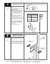
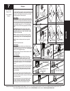
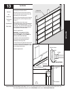
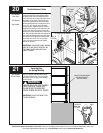
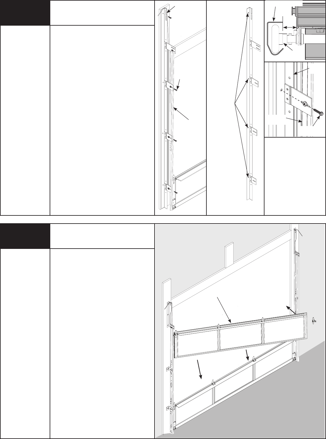
Stacking Sections
Power Drill
7/16” Socket
Driver
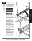
LOCK SECTION
NOTE: For door section identification see page 4.
NOTE: Make sure hinges are flipped down, when
stacking another section on top.
With assistance, lift second section and guide
roller into the left vertical track. Stack this
section into the opening by hooking the roller
into the left hand vertical track and lowering
the section onto the bottom section, as shown.
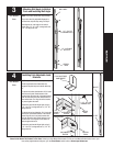
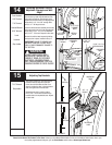
Insert a roller into the proper, uninstalled right
hand end hinge, and place the roller into the
right hand vertical track. Lower the roller and
hinge into the proper position over the section,
and attach to the section in the same manner
the left hand end hinge was attached in step 7.
Keeping the ends of the sections aligned, install
remaining section(s), except top section, in same
manner. Now flip up hinge leaf, hold tight against
section, and fasten center hinges first, and end
hinges last, using (2) 1/4” x 7/8” self drilling
screws. Repeat for other section(s) except top
section.
IMPORTANT: PUSH & HOLD THE HINGE LEAF
AGAINST SECTION WHILE SECURING WITH 1/4” X
5/8” SELF TAPPING SCREWS.
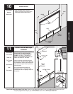
NOTE: Install lock at this time (sold separately)
see instructions in OPTIONAL SIDE LOCK
INSTALLATION on page 24.
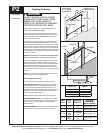
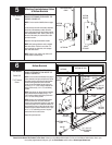
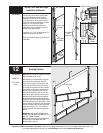
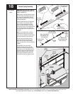
Position the left hand vertical track assembly
over the rollers of the bottom section. Make
sure the counterbalance cable is located
between the rollers and the door jamb. Drill
3/16” pilot holes for the lag screws. Loosely
fasten the vertical track assembly to the jamb
using 5/16” x 2” lag screws. Tighten
bottom lag screw securing vertical track
assembly to jamb, to maintain 5/8” spacing.
Repeat for the right hand side.
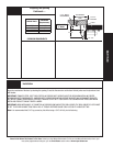
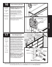
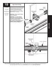
Tighten the 1/4” x 5/8” carriage bolts and 1/4”
flange hex nuts of each clip plates.
Hang counterbalance cables over vertical track
assemblies.
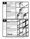
WALL ANGLE
HOLE
SELECTION
5/16” X 2”
LAG BOLT
WALL
ANGLE
VERTICAL
TRACK
Vertical Track and Wall Angle
Installation Continued....
VERTICAL TRACK
ROLLER
3/8 -
5/8”
WALL ANGLE
5/16 X 2” LAG
SCREWS
WALL ANGLE
ASSEMBLY
BOTTOM
SECTION