


12
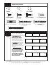
Please Do Not Return This Product To The Store. Contact your local Wayne-Dalton dealer. To find your local Wayne-Dalton dealer, refer to your
local yellow pages/business listings or go to the Find a Dealer section online at www.wayne-dalton.com
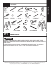
Tools Needed:
Tools Needed:
Tools Needed:
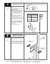
8
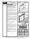
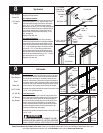
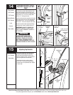
Top Bracket
Power Drill
7/16” Socket
Driver
NOTE: Top brackets are attached 1-3/4” down from the
top edge of the top section..
For single top brackets:
Place a top bracket onto the top left hand corner of the
top section and down 1-3/4”. Align the edge of the
top bracket with the edge of the section, and secure
using (2) 1/4” x 7/8” self drilling screws in the top
door section rail and (2) 1/4” x 7/8” self drilling screws
into the stile as shown. Place the top bracket slide on
top of the top bracket base. Loosely secure the top
bracket slide to the top bracket base using (1) 1/4 x
5/8” carriage bolt.
Repeat for the other side.
For double top brackets:
Position another top bracket next to the previously
installed top bracket as shown. Leave space between
the brackets to allow the top bracket slides to move
freely. Secure the top bracket to the section using (2)
1/4” x 7/8” self drilling screws in the top door section
rail and (2) 1/4” x 7/8” self drilling screws into the
stile as shown. Place the top bracket slide on top of
the top bracket base. Loosely secure the top bracket
slide to the top bracket base using (1) 3/8” - 16 x 3/4”
hex head bolt and a 3/8” x 16 hex nut.
Repeat for the other side.
(4) 1/4” X 7/8” SELF
DRILLING SCREWS
TOP BRACKET
BASE
END STILE
TOP SECTION
TOP SECTION
TOP
BRACKET
BASE
TOP SECTION
TOP
BRACKET
ASSEMBLY
(1) 3/8” - 16
HEX NUT
(1) 3/8” - 16 X 3/4”
HEX HEAD BOLT
TOP
BRACKET
SLIDE
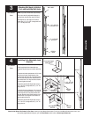
9
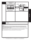
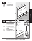
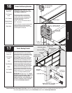
Lift Handle
Bottom section
Locate the center most stile of the bottom section of the door.
On the inside of the door, center the lift handle vertically with
the center stile; horizontally on the bottom section rail, and
within 8” of the bottom of the section. Using the lift handle as
a template, place a mark at each hole location onto the bottom
section rail. Drill a 9/32” diameter through the section at each
marked location. Be extremely careful to keep drill straight.
Assemble the outside and inside lift handle to the section using
(4) 1/4” x 7/8” self drilling screws.
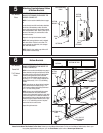
Lock (2nd) section
Locate the center most stile on the lock (2nd) section of the
door. Position the lift handle’s bottom hole 4” from the bottom
of the lock (2nd) section. Center the lift handle vertically on
the center stile and vertically align with the lift handle on the
bottom section. Using the lift handle as a template, place
mark at each hole location onto the center stile. Drill a 9/32”
diameter through the section at each marked location. Be
extremely careful to keep drill straight.
Assemble the outside and inside lift handle to the section using
(4) 1/4” x 7/8”.
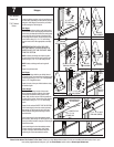
TO AVOID POSSIBLE INJURY, LIFT HANDLES THAT ARE
INSTALLED WITHIN 4 INCHES OF A SECTION INTERFACE
SHALL PROMOTE VERTICAL ORIENTATION OF THE HAND.
LIFT HANDLE OUTSIDE
LIFT HANDLE INSIDE
Tape Measure
Pencil
Power Drill
9/32” Drill Bit
1/2” Drill Bit
1/4” Wrench
Vice Clamps
LOCK
SECTION
LOCK
SECTION
LOCK
SECTION
LOCK
SECTION
BOTTOM
SECTION
BOTTOM
SECTION
BOTTOM
SECTION
BOTTOM SECTION
LIFT
HANDLE
LIFT
HANDLE
LIFT
HANDLE
LIFT
HANDLE
(2) 1/4”
HEX NUTS
(2) 1/4” X 7/8”
SELF DRILLING
SCREWS
WARNING
1-3/4” DOWN
FROM EDGE OF
TOP SECTION