


11
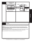
Please Do Not Return This Product To The Store. Contact your local Wayne-Dalton dealer. To find your local Wayne-Dalton dealer, refer to your
local yellow pages/business listings or go to the Find a Dealer section online at www.wayne-dalton.com
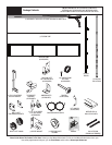
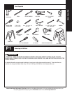
Tools Needed:
INSTALLATION
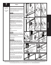
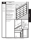
NOTE: For door section identification see page 4.
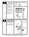
Locate the bottom section, using #1 end hinges for
the end stiles; depending on the width of your door
enough #1 half hinges for each of the pre-drilled
locations along the reinforcing fin.
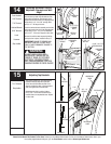
End Hinges:
Place (1) #1 end hinge at the top left hand corner
of the bottom section. Vertically align the slot/hole
of the lower (numbered) leaf with the small groove
in the end stile, and the center of the hinge with
the top edge of the section. Secure the end hinge
to the section using (2) 1/4” x 7/8” self drilling
screws. Insert a roller into appropriate end hinge
tube.
IMPORTANT: WHEN PLACING ROLLERS
INTO END HINGES, THE ROLLER MUST BE
INSERTED INTO THE TUBE FURTHEST AWAY
FROM THE SECTION.
NOTE: If double end hinges are required, place
the second end hinge on the inner end stile and
secure using (2) 1/4” x 7/8” self drilling screw.
NOTE: Double end hinges will use long shaft
rollers.
Repeat for right hand side.
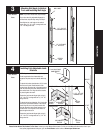
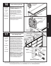
Half Hinges:
Align the half hinge with the pre-drilled holes of
the reinforcing fin, and secure the half hinge to the
reinforcing fin using (2) 1/4” x 5/8” Carriage Bolts
and (2) 1/4” Flanged Hex Nuts.
Repeat for each of the pre-drilled locations along
the reinforcing fin.
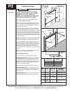
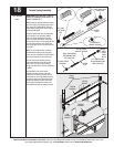
Center Hinges:
Place (1) #1 end hinge at each of the center
stiles. Vertically align the slot/hole of the lower
(numbered) leaf with the small groove in the
center stiles, and the center of the hinge with the
top edge of the section. Secure the center hinges
to the section using (2) 1/4” x 7/8” self drilling
screw.
Repeat for all sections EXCEPT THE TOP SECTION.
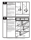
Use #2 end hinges for the lock section (second),
and enough #1 half hinges for each of the pre-
drilled locations along the reinforcing fin of the
second section.
Use #3 end hinges for the intermediate section
(third section), and enough #1 half hinges for each
of the pre-drilled locations along the reinforcing fin
of the third section.
Use #4 end hinges for the intermediate section
II (fourth section), and enough #1 half hinges
for each of the pre-drilled locations along the
reinforcing fin of the intermediate II section.
7
Hinges
Power Drill
7/16” Socket
Driver
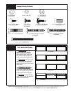
#1 HINGE #2 END HINGE
#3 END HINGE #4 END HINGE
ROLLER
PLACEMENT
ROLLER
PLACEMENT
ROLLER
PLACEMENT
HINGE
CENTER STILE
#1
HALF
HINGE
CENTER
STILES
CENTER HINGE PLACEMENT AND BEING ASSEMBLED
CENTER HINGE BEING ASSEMBLED
(2)1/4”- 20 X 5/8”
CARRIAGE BOLTS
(AS REQUIRED)
(2) 1/4” X 20
FLANGE HEX
NUT
#1 HALF HINGES
(2) 1/4” X 7/8”
SELF DRILLING
SCREWS
(8) 1/4” X 7/8” SELF
DRILLING SCREWS
PRE-
DRILLED
HOLES
(4) 1/4” X 7/8” SELF
DRILLING SCREWS
#1
HINGE
(2) 1/4” X 7/8” SELF
DRILLING SCREWS
1/4” SPACING
BETWEEN HINGES
CENTER
STILE
HINGE
CENTER HINGE ASSEMBLED