


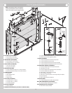
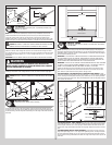
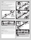

Inside step plate
Bottom section inside
(2) #8 Screws
8” Max.
mounting
height
Outside
step plate
Bottom section outside
7/16”
Diameter holes
Drill (1) 7/16”
diameter hole
at each marked
location
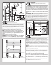
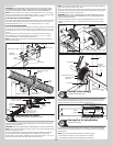
Lift Handle
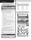
Tools Required: Pencil, Power Drill, (9/32”, 1/2”) Drill Bits, Saw horses, Tape
Measure, 7/16” Wrench
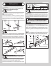
10
NOTE: Refer to door section identification, located in the pre-installation section of this
manual to determine what size sections you need to use as your lock (second) section.
Locate the vertical center of the lock (second) section of the door and position the lift
handle’s bottom hole 4” from the bottom of the lock section along the vertical center on the
outside of the door. Use the holes in the lift handle as a template to mark the hole locations.
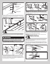
CAUTION: BE CAREFUL TO KEEP DRILL STRAIGHT WHEN PRE-DRILLING. SECTION
DAMAGE CAN RESULT FROM FAILURE TO KEEPING THE DRILL STRAIGHT.
IMPORTANT: THE LIFT HANDLE AND THE STEP PLATE NEED TO BE VERTICALLY ALIGNED.
Drill 9/32” diameter holes through the section at each marked location. Enlarge the holes
from outside the door to 1/2” diameter through the section. Assemble the outside and inside
lift handles to the section using (2) 1/4” x 2-1/2” carriage bolts and (2) 1/4” - 20 hex nuts
and spacers.
IMPORTANT: THE LIFT HANDLE AND THE STEP PLATE NEED TO BE VERTICALLY ALIGNED.
WARNINGWARNING
TO AVOID POSSIBLE INJURY, LIFT HANDLES THAT ARE INSTALLED
WITHIN 4 INCHES (102MM) OF A SECTION INTERFACE SHALL PROMOTE
VERTICAL ORIENTATION OF THE HAND.
NOTE: You may need to cut off the protruding ends of the carriage bolts after securing the lift
handle(s) to the section. If the carriage bolts are cut off, use a file to smooth rough edges.
CAUTION: FAILURE TO SMOOTH CARRIAGE BOLT ENDS MAY RESULT IN POSSIBLE
INJURY.
1/2” Diameter
holes
4”
(2)
Spacers
(2) 1/4”-20 x 2-1/2” Carriage bolts
Lock
section
outside
Lock
section
inside
Lift handle
(2) 1/4”-20
Hex nuts
Lift handle
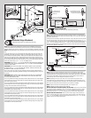
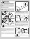
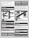
Bottom Section
Tools Required: Level, Wooden shims (if necessary)
11
Center the bottom section in the door opening. Level the section using wooden shims (if
necessary) under the bottom section. When the bottom section is leveled, temporarily hold it
in place by driving a nail into the jamb and bending it over the edge of the bottom section on
both sides.
Weather seal
Level
Bottom section
Wooden shims
(If necessary)
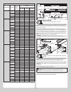
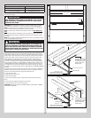
Vertical Tracks
Tools Required: Power Drill, 3/16” Drill bit, 7/16” Socket driver, Tape measure,
Level, Step ladder
12
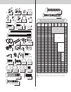
NOTE: Depending on your door, you may have Quick Install Flag Angles, Fully Adjustable
Flag Angles, Riveted Vertical Track Assemblies or you may have Angle Mount Vertical Track
Assemblies. Refer to Package Contents / Parts Breakdown, to determine which Flag Angles /
Vertical Track Assemblies you have.
IMPORTANT: IF YOUR DOOR IS TO BE INSTALLED PRIOR TO A FINISHING CONSTRUCTION
OF THE BUILDING’S FLOOR, THE VERTICAL TRACKS AND THE DOOR BOTTOM SECTION
ASSEMBLY SHOULD BE INSTALLED SUCH THAT WHEN THE FLOOR IS CONSTRUCTED, NO
DOOR OR TRACK PARTS ARE TRAPPED IN THE FLOOR CONSTRUCTION.
IMPORTANT: THE TOPS OF THE VERTICAL TRACK ASSEMBLIES MUST BE LEVEL FROM SIDE
TO SIDE. IF THE BOTTOM SECTION WAS SHIMMED TO LEVEL IT, THE VERTICAL TRACK AS-
SEMBLY ON THE SHIMMED SIDE MUST BE RAISED THE HEIGHT OF THE SHIM.
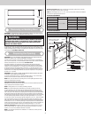
Position the left hand vertical track assembly over the track rollers of the bottom section.
Make sure the counterbalance lift cable is located between the track rollers and the door
jamb. Drill 3/16” pilot holes into the door jamb for the lag screws.
FOR QUICK INSTALL FLAG ANGLES OR FULLY ADJUSTABLE FLAG ANGLES: Loosely
fasten jamb brackets and flag angle to the jamb using 5/16” x 1-5/8” lag screws. Tighten lag
screws, securing the bottom jamb bracket to jamb, maintain 3/8” to 5/8” spacing, between
the bottom section and vertical track. Hang counterbalance lift cable over flag angle. Repeat
same process for other side.
Vertical
track
assembly
Jamb
bracket
Flag
angle
Flag angle lag screw locations
5/16” x 1-5/8”
Lag screws
Bottom
section
Track
rollers
12R FA
3/8” to 5/8”
Spacing
Bottom section
Vertical track
15R FA 15R QI12R QI
Floor
Track roller
FOR RIVETED VERTICAL TRACK ASSEMBLY: Loosely fasten jamb brackets and flag angle
to the jamb using 5/16” x 1-5/8” lag screws. Tighten lag screws, securing the bottom jamb
bracket to jamb, maintain 3/8” to 5/8” spacing as shown between the bottom section and
vertical track. Hang counterbalance lift cable over flag angle. Repeat same process for other
side.
FOR ANGLE MOUNT VERTICAL TRACK ASSEMBLY: Loosely fasten the slots in the wall
angle to the jamb using 5/16” x 1-5/8” lag screws. Tighten lag screws, securing the bottom
slot in the wall angle, maintain 3/8” to 5/8” spacing as shown between the bottom section
and vertical track. Hang counterbalance lift cable over angle mount. Repeat same process for
other side.
9