


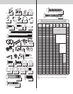
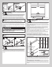
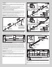

(4) 1/4”-14 x 7/8”
Self drilling screws
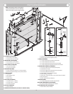
Bottom section
1/4”-14 x 5/8” Tamper
resistant self drilling screw
Inside portion of
left hand bottom
bracket
End cap
Left hand
bottom
bracket
5/16”
Washer
Cotter
pin
Clevis
pin
Counterbalance
cable loop
Clevis
pin
Roller spacer
Short stem
track roller
Counterbalance
lift cable
Counterbalance lift cable
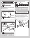
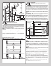
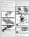
Graduated Hinge Attachment
Tools Required: Power Drill, 7/16” Socket driver, Saw horses
5
NOTE: Refer to door section identification, located in the pre-installation section of this
manual to determine what size sections you need to use as your lock and intermediate(s)
sections. Measure your section to make sure it is the correct height as indicated on the chart.
NOTE: The graduated hinges can be identified by the number stamped onto their lower hinge
leaf.
Locate the bottom section, (2) #1 graduated end hinges (wide body) for the end stiles and
depending on the width of your door, enough #1 center hinge(s) (narrow body) for each of
the pre-marked center hinge locations. Starting on the left hand side of the bottom section,
align the lower hinge leaf of the #1 graduated end hinge over the holes, located at the top
of the end caps. Also, align the lower hinge leafs of the #1 center hinges (narrow body) with
the pre-marked locations at the center locations at the top of the section. Attach lower hinge
leafs to the section using (2) 1/4” - 14 x 7/8” self drilling screws.
IMPORTANT: ONCE THE 1/4” - 14 X 7/8” SELF DRILLING SCREWS ARE SNUG AGAINST THE
LOWER HINGE LEAFS, TIGHTEN AN ADDITIONAL 1/4 TO 1/2 TURN TO RECEIVE MAXIMUM
DESIGN HOLDING POWER.
IMPORTANT: PUSH & HOLD THE HINGE LEAF SECURELY AGAINST THE SECTION WHILE
SECURING WITH 1/4” - 14 X 7/8” SELF DRILLING SCREWS. THERE SHOULD BE NO GAP
BETWEEN THE HINGE LEAF AND THE SECTION.
Place a short stem track roller into each graduated end hinge. Repeat graduated hinge at-
tachment using the appropriate graduated end hinges for all remaining sections, except the
top section.
IMPORTANT: WHEN PLACING SHORT STEM TRACK ROLLERS INTO THE #2 GRADUATED
END HINGES AND HIGHER, THE SHORT STEM TRACK ROLLER GOES INTO HINGE TUBE
FURTHEST AWAY FROM SECTION.
Use (2) #2 graduated end hinges (wide body) and the required number of #1 center hinge(s)
(narrow body) for each of the center hinge pre-marked location(s) along the top edge of the
lock section (second section).
Use (2) #3 graduated end hinges (wide body) and the required number of #1 center hinge(s)
(narrow body) for each of the center hinge(s) (narrow body) pre-marked location(s) along the
top edge of the intermediate I section (third section).
Use (2) #4 graduated end hinges (wide body) and the required number of #1 center hinge(s)
(narrow body) for each of the center hinge pre-marked location(s) along the top edge of the
intermediate II section (fourth section).
Use (2) #5 graduated end hinges (wide body) and the required number of #1 center hinge(s)
(narrow body) for each of the center hinge pre-marked location(s) along the top edge of the
intermediate III section (fifth section).
Use (2) #6 graduated end hinges (wide body) and the required number of #1 center hinge(s)
(narrow body) for each of the center hinge pre-marked location(s) along the top edge of the
intermediate IV section (Sixth section).
Use (2) #7 graduated end hinges (wide body) and the required number of #1 center hinge(s)
(narrow body) for each of the center hinge pre-marked location(s) along the top edge of the
intermediate V section (seventh section).
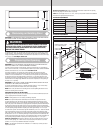
#1Center hinge(s)
(Narrow body)
#1 Graduated end
hinge (Wide body)
Lower leaf
#2 Graduated end hinge
(roller inserted into tube
furthest from section)
(2) 1/4”-14 x 7/8” Self
drilling screw locations
Pre-punched
holes in
endstiles
Pre-marked
locations on
section surface
Short stem
track roller
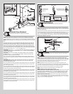
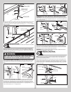
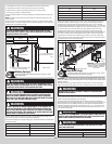
Top Fixtures (A)
Tools Required: Power drill, 7/16” Socket driver, Saw horses
6
NOTE: Using the illustrations below and referring to Package Contents / Parts Breakdown, to
determine if you have Top Fixture Bases and Top Fixture Slides or not. If you have Top Fixture
Assemblies, skip this step.
Starting on the left hand side, align the top fixture base on top of the corner of the top section
and even with the edge of the section. Fasten to section through end cap using (4) 1/4” - 14
x 7/8” self drilling screws. Loosely secure the top fixture slide to the top fixture base using (1)
5/16” - 18 x 3/4” carriage bolt and (1) 5/16” - 18 hex nut. The top fixture assembly will be
tightened and adjusted later, in step, Adjusting Top Fixtures. Insert short stem track roller into
top fixture slide. Repeat for other side.
5/16”-18 x 3/4”
Carriage bolt
(4) 1/4”-20 x 7/8”
Self drilling screws
Top fixture
base
Top fixture
slide
5/16”-18
Hex nut
End
cap
Top section
Short stem
track roller
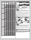
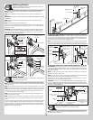
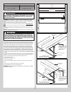
Strutting
Tools Required: Power drill, 7/16” Socket driver, Saw horses, Tape measure
7
NOTE: Refer to door section identification, located in the pre-installation section of this
manual to determine what size sections you need to use as your lock (second) section, inter-
mediate (third) section, intermediate (fourth) section, intermediate (fifth) section, intermediate
(sixth) section, intermediate (seventh) section and top section. Measure your sections to
make sure they are the correct height as indicated on the chart.
NOTE: Depending on the size of your door, one or more sections may require a strut.
Using sawhorses, lay sections together on a flat smooth surface. Ensure the hinges are on
top of their corresponding sections. Referring to the strutting schedule, determine how many
struts your door needs and on what sections they are needed to be installed.
NOTE: Sections not noted in the strutting schedule, do not require a strut.
NOTE: All strut(s) are placed at the top of the section(s).
INSTALLATION ON ALL SECTIONS (EXCEPT TOP SECTION): Place the strut on the section
up against the bottom of the hinges. Center the strut side to side on the section, as shown.
Secure the strut to the section using (2) 1/4” - 14 x 7/8” self drilling screws at each end
hinge location and (2) 1/4” - 14 x 7/8” self drilling screws at each center hinge location.
INSTALLATION ON TOP SECTION: Place the strut on the top edge of the top section, as
shown. Center the strut side to side on the section. Secure the strut to the section using (2)
1/4” - 14 x 7/8” self drilling screws at each end hinge location and (2) 1/4” - 14 x 7/8” self
drilling screws at each center hinge location.
7