


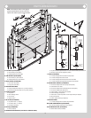
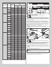
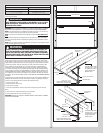

End Bearing Brackets
Tools Required: Step ladder, Power drill, 3/16” Drill bit, Ratchet wrench, 7/16”
Socket driver, 9/16” Socket, 9/16” Wrench
18
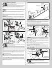
NOTE: Refer to Package Contents / Parts Breakdown, to determine which End Bearing
Brackets you have.
NOTE: Prior to fastening end bearing brackets into the door jamb, pilot drill using a 3/16”
drill bit.
IMPORTANT: RIGHT AND LEFT HAND IS ALWAYS DETERMINED FROM INSIDE THE BUILDING
LOOKING OUT.
NOTE: Depending on your door’s configuration you may have to break the end bearing
brackets apart.
NOTE: End bearing brackets are right and left hand.
Attach the left hand end bearing bracket through either the end bearing bracket’s upper or
lower slots to the left hand horizontal track angle using (2) 3/8” - 16 x 3/4” truss head bolts
and (2) 3/8” - 16 nuts.
IMPORTANT: THE END BEARING BRACKET’S LOWER SLOTS ARE USED ON DOORS WITH
12” RADIUS TRACK; THE UPPER SLOTS ARE USED ON DOORS WITH 15” RADIUS TRACK.
Secure the top of the end bearing bracket to the jamb using 5/16” x 1-5/8” lag screw(s).
Repeat the same process for right hand side.
(2) 3/8”-16
Hex nuts
(2) 3/8”-16 x 3/4”
Truss head bolts
Left end bracket
Upper slots
Lower slots
Horizontal track angle
(1) 5/16” x 1-5/8”
Lag screw
Bend back and fourth to
seperate the (2) end
bearing brackets
(2) 3/8”-16
Hex nuts
(2) 3/8”-16 x 3/4”
Truss head bolts
Left end
bracket
Upper
slot
Lower slots
Horizontal
track angle
(3) 5/16” x 1-5/8”
Lag screws
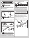
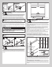
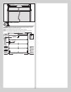
Center Bracket
Tools Required: Step ladder, Power drill, 7/16” Socket driver, 3/16” Drill bit, 1/4”
Torx bit, Level, Tape measure, Pencil
19
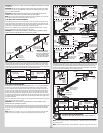
NOTE: Refer to Package Contents / Parts Breakdown, to determine which Center Bracket(s)
came with your door.
NOTE: Prior to fastening center bracket(s) into the door jamb, pilot drill using a 3/16” drill bit.
NOTE: Refer to Package Contents / Parts Breakdown, to determine if your door came with a
coupler assembly. If your door came with a coupler assembly, the mounting surface needs to
be a minimum of 17” wide. The two center bearing brackets will need to be spaced 12” to
14” apart at the center of the door, as shown.
NOTE: If your door came with (4) springs, each of the outer springs mounting surface will
need to be a minimum of 3” wide.
NOTE: If needed, measure the diameter of your springs. If you have a one piece shaft with
3-3/4” diameter springs, they do not share center brackets and do not have a coupler as-
sembly.
First, locate the center of the door. Mark a vertical pencil line on the mounting surface above
the door, at the center. Measure from the center of the bearing, in one of the end bearing
brackets, downwards, to the top the door. Using that measurement, measure that distance
upwards from the top of the door to the mounting surface and mark a horizontal pencil line
which intersects the vertical pencil line.
Typicall center
bracket
Vertical line
Mounting surface
Equal distance (top of door section to horizontal line)
Horizontal line
Typicall center
of end bearing
bracket
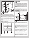
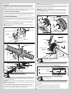
IF YOUR DOOR DID NOT COME WITH A CENTER COUPLER ASSEMBLY OR TORSION
SPRINGS LESS THAN 3-3/4” ID: Mark a vertical pencil line on the mounting surface above
the door, at the center. Align the edge of the center bracket with the vertical pencil line and
the center of the center bracket with the horizontal pencil line; this is to ensure the torsion
shaft is level between the center and end bearing brackets.
NOTE: On some single spring doors, the single spring can be longer than half the opening
width. If your spring is longer, then the center bracket must be mounted off center for the
spring to fit properly. Measure spring length to determine appropriate center bracket location.
Center bracket
bushing assembly
(1) 5/16” X 2” or (1) 5/16” x 1-5/8” Tamper-resistant lag screw
(2) 5/16” x 1-5/8”
Lag screws
Vertical
line
Mounting
surface
(3” Minimum)
Horizontal
line
Vertical
line
Mounting surface
(3” Minimum)
Horizontal
line
Center
bearing
bracket
assembly
(2) 5/16” x 1-5/8”
Lag screws
IF YOUR DOOR DID COME WITH A CENTER COUPLER ASSEMBLY OR 3-3/4” ID TOR-
SION SPRINGS: Mark a vertical pencil line on the mounting surface above the door, at the
center. Split the difference up and position the (2) center bearing brackets apart from each
other. Mark two vertical pencil lines, one for each center bearing bracket onto the mounting
surface above the door.
NOTE: If your door came with a center coupler assembly or if it utilizes 3-3/4” springs, the
springs will not share a center bracket.
NOTE: If your door has (4) springs, split the distance between the center of the door and the
end bracket on each side to locate the intermediate center brackets.
Attach each of the center bracket(s) to the mounting surface, using (2) 5/16” x 1-5/8” lag
screws and (1) 5/16” x 2” tamper-resistant lag screw.
IMPORTANT: USE A 5/16” X 1-5/8” TAMPER-RESISTANT LAG SCREW INSTEAD OF THE
5/16” X 2” TAMPER-RESISTANT LAG SCREW IF MOUNTING SURFACE IS MOUNTED OVER
MASONRY. TAMPER-RESISTANT LAG SCREW MUST BE ATTACHED THROUGH THE BOTTOM
HOLE OF THE CENTER BRACKET(S).
(1) 5/16” X 2” or (1) 5/16”
x 1-5/8” Tamper-resistant
lag screw
Vertical
line
Mounting surface
(17” Minimum)
Horizontal
line
(2) 5/16” x 1-5/8”
Lag screws
Vertical line
(2) 5/16” x 1-5/8”
Lag screws
† (2) Center bearing
brackets spaced 6” to 7”
apart from the center of
the door.
Center
of
door
†
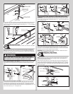
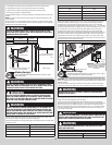
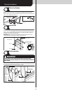
Torsion Spring Assembly
Tools Required: 3/8” Wrench, 9/16” Wrench, Step Ladder
20
NOTE: Refer to the Package Contents and or Parts Breakdown to determine if your door
came with a coupler assembly.
12