


INSTALLATION
Before installing your door, be certain that you have read and followed all of the instruc-
tions covered in the pre-installation section of this manual. Failure to do so may result in an
improperly installed door.
NOTE: Reference TDS 160 for general garage door terminology at www.dasma.com.
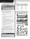
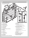
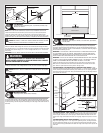
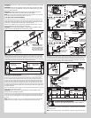
Fully Adjustable Flag Angles
Tools Required: None
1
NOTE: If you have Quick Install flag angles, Riveted Track or Angle Mount Track, skip this
step.
NOTE: Flag angles are right and left handed.
If you have Quick Install vertical tracks, hand tighten the left hand flag angle to the left hand
vertical track using (1) stud plate and (2) 1/4” - 20 flange hex nuts. Repeat for the other side.
If you have Fully Adjustable vertical tracks, hand tighten the left hand flag angle to the left
hand vertical track using (2) 1/4” - 20 x 9/16” track bolts and (2) 1/4” - 20 flange hex nuts.
Repeat for other side. Flange nuts will be secured after flag angle spacing is completed in
step, Top Section.
Quick Install
vertical
track
Stud
plate
Flag angle
1/4”-20
Flange hex nuts
1/4”- 20 x 9/16”
Track bolts
Flag angle
Fully Adjustable
vertical
track
1/4”-20
Flange hex nuts
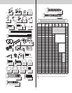
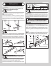
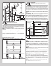
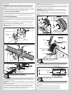
Horizontal Track Angles
Tools Required: Hammer
2
NOTE: For larger doors, a full length horizontal track angle may not already be spot welded to
the horizontal track. If the horizontal track angle is not welded, the horizontal track angle will
be installed, as shown.
Position the left hand horizontal track angle, as shown. Place the Quick Install tabs of the
horizontal track angle in the key slot of the left hand horizontal track. Using a hammer, tap
the horizontal track angle towards the curved end of the track until the alignment hole in the
track and angle are aligned. Repeat for other side. Set tracks aside.
Horizontal track
angle
Key slots
Horizontal
track
Alignment
hole
Quick
Install
tabs
Quick Install tabs
in place
Horizontal track
angle
Key slots
Horizontal
track
Quick
Install tabs
Quick Install tabs
in place
Horizontal
track
Horizontal track
angle
Quick
Install tabs
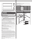
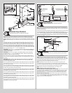
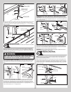
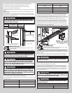
Bottom Weather Seal
Tools Required: Power Drill, 7/16” Socket driver, Tape measure, Saw horses
3
NOTE: Refer to door section identification, located in the pre-installation section of this
manual to determine what size section you need to use as your bottom section. Measure
your section to make sure it is the correct height as indicated on the chart.
Align the ends of the bottom weather seal with the bottom of the bottom section. Attach bot-
tom weather seal to the section using 1/4” - 14 x 7/8” self drilling screws, one on each end
at least 6” from the end of the section and one every 18” in between.
Bottom section
1/4”-14 x 7/8” Self
drilling screws
Bottom section
Bottom
weather seal
6”
18” 18”18”
6”
18”
1/4”-14 x 7/8”
Self drilling
screws
Bottom
weather seal
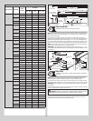
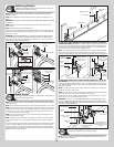
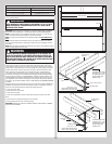
Counterbalance Lift Cables and Rollers
Tools Required: Power Drill, 7/16” Socket driver, Tape measure, Saw horses
4
NOTE: Refer to Package Contents / Parts Breakdown, to determine which bottom corner
brackets you have.
Uncoil the counterbalance lift cables. Depending on which bottom corner brackets you have
(reference illustrations below), slip the loop at the ends of the counterbalance lift cable over
the milford pin of the bottom corner bracket or secure the cable loop to the clevis pin and
bottom corner bracket using a 5/16” flat washer and a cotter pin. Repeat for other bottom
corner bracket.
WARNINGWARNING
FAILURE TO ENSURE TIGHT FIT OF CABLE LOOP OVER MILFORD PIN
COULD RESULT IN COUNTERBALANCE LIFT CABLE COMING OFF THE PIN,
ALLOWING THE DOOR TO FALL, POSSIBLY RESULTING IN SEVERE OR
FATAL INJURY.
Starting on the left hand side, attach the left hand bottom corner bracket to the left corner of
the bottom section, making sure it is seated to the edges of the end cap, using 1/4” - 14 x
7/8” self drilling screws and (1) 1/4” - 14 x 5/8” tamper resistant self drilling screw. Repeat
for right hand bottom corner bracket.
NOTE: All doors are provided with the tamper resistant fastener for the bottom corner
brackets. However, the professional installer is most likely to have the proper tool to install
this fastener. If the homeowner does not have the proper tool to install the tamper resistant
fastener, use a regular 1/4” - 14 x 7/8” self drilling screw in its place.
NOTE: Check to ensure cable loop fits tightly over the milford pins.
Insert a short stem track roller with roller spacer into the bottom corner bracket. Repeat for
other side.
NOTE: Verify bottom weather seal (bottom seal) is aligned with door section. If there is more
than 1/2” excess bottom weather seal on either side, trim bottom weather seal even with
door section.
(5) 1/4”-14 x 7/8”
Self drilling screws
1/4”-14 x 5/8” Tamper
resistant self drilling screw
Bottom corner
bracket
End
cap
Roller spacer
Short stem
track roller
Counterbalance
cable loop
Counterbalance
lift cable
Milford pin
Bottom
section
Bottom
weather seal
6