


Flag angle lag screw
locations
3/8” to 5/8”
Spacing
Bottom section
Vertical track
Bottom section
Vertical
track
Jamb
bracket
Flag
angle
5/16” x 1-5/8”
Lag screws
Floor
Angle mount
vertical track
assembly
Bottom
section
Riveted
vertical track
assembly
5/16” x 1-5/8”
Lag screws
Vertical
track
Wall
angle
Slot
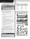
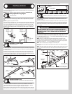
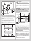
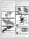
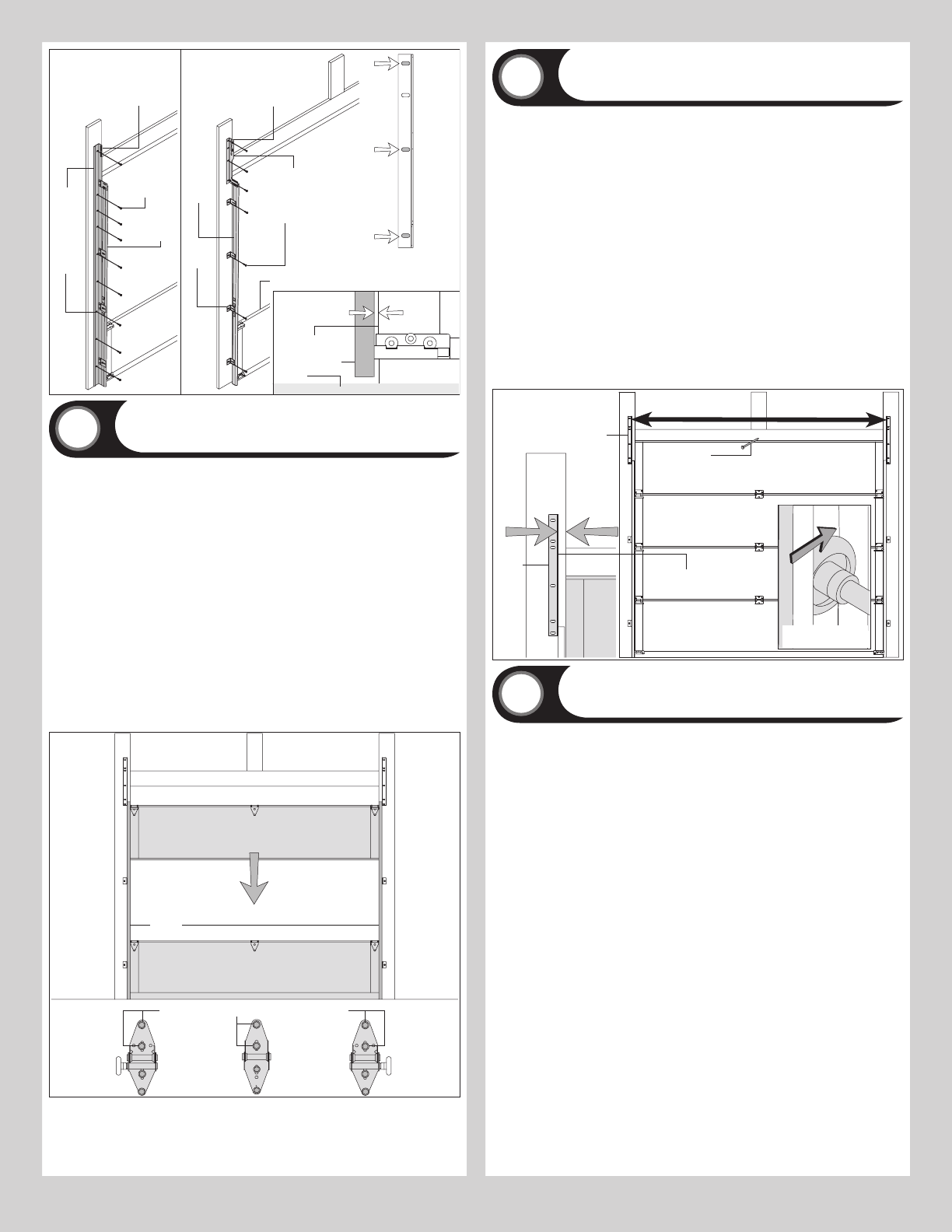
Stacking Sections
Tools Required: Power drill, 7/16” Socket driver
13
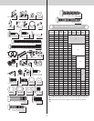
NOTE: Refer to door section identification, located in the pre-installation section of this
manual to determine what size sections you need to use as your lock (second) section, inter-
mediate (third) section, intermediate (fourth) section, intermediate (fifth) section, intermediate
(sixth) section and intermediate (seventh) section. Measure your sections to make sure they
are the correct height as indicated on the chart.
NOTE: Make sure graduated end and center hinges are flipped down, when stacking another
section on top.
Place short stem track rollers into graduated end hinges of remaining sections.
NOTE: Larger doors will use long stem track rollers with double graduated end hinges.
With assistance, lift second section and guide the track rollers into the vertical tracks. Lower
section until it is seated against bottom section. Keep sections aligned and fasten center
hinge(s) first; then graduated end hinges last using (2) 1/4” - 14 x 7/8” self drilling screws,
per hinge.
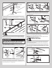
Repeat same process for other sections, except top section.
IMPORTANT: PUSH & HOLD THE HINGE LEAFS SECURELY AGAINST THE SECTIONS WHILE
SECURING WITH 1/4” - 14 X 7/8” SELF DRILLING SCREWS. THERE SHOULD BE NO GAP
BETWEEN THE HINGE LEAFS AND THE SECTIONS.
NOTE: Install lock at this time (sold separately). See optional installation step, Side Lock.
Lock section
Vertical
tracks
Center
hinge(s)
Left
graduated
end hinge
Right
graduated
end hinge
1/4”-14 x 7/8” Self drilling screw locations
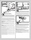
Bottom section
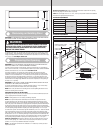
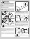
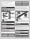
Top Section
Tools Required: 7/16” Wrench, Hammer, Step ladder, Tape measure
14
Place the top section in the opening. Temporarily secure the top section by driving a nail in
the header near the center of the door and bending it over the top section. Now, flip up the
hinge leaves, hold tight against section, and fasten center hinges first and end hinges last
(refer to step, Stacking Sections). Vertical track alignment is critical. Position flag angle or wall
angle between 1-11/16” (43 mm) to 1-3/4” (44 mm) from the edge of the door; tighten the
bottom lag screw. Flag angles or wall angles must be parallel to the door sections. Repeat for
other side.
IMPORTANT: THE DIMENSION BETWEEN THE FLAG ANGLES OR WALL ANGLES MUST BE
DOOR WIDTH PLUS 3-3/8” (86MM) TO 3-1/2” (89 MM) FOR SMOOTH, SAFE DOOR OPERA-
TION.
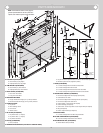
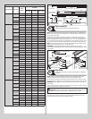
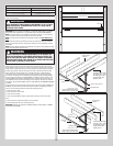
FOR QUICK INSTALL TRACK: Complete the vertical track installation by securing the jamb
bracket(s) and tightening the other lag screws. Repeat for other side.
FOR FULLY ADJUSTABLE TRACK OR RIVETED TRACK: Complete the vertical track instal-
lation by securing the jamb bracket(s) and tightening the other lag screws. Push the vertical
track against the track rollers so that the track rollers are touching the deepest part of the
curved side of the track; tighten all the track bolts and nuts. Repeat for other side.
FOR ANGLE MOUNT TRACK: Complete the vertical track installation by securing the jamb
bracket(s) and or tightening the other lag screws. Push the vertical track against the track
rollers so that the track rollers are touching the deepest part of the curved side of the vertical
track, as shown. Repeat for other side.
Top section
Top
section
Nail
Door width
+ 3-3/8” to 3-1/2”
1-11/16”
to 1-3/4”
Flag
angle
Vertical track
against track rollers
Flag angle or
wallangle assembly
Top of flag angle or
Top of wallangle assembly
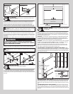
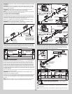
Drawbar Operator Bracket
Tools Required: Level, Power drill, 7/16” Socket driver, Tape measure
15
NOTE: Refer to the Package Contents and or Parts Breakdown to determine if your door
came with a drawbar operator bracket. If you did not receive a drawbar operator bracket, skip
this step.
IMPORTANT: WHEN CONNECTING A DRAWBAR OPERATOR TYPE GARAGE DOOR OPENER
TO THIS DOOR, A WAYNE-DALTON OPERATOR/ DRAWBAR OPERATOR BRACKET MUST
BE SECURELY ATTACHED TO THE TOP SECTION OF THE DOOR, ALONG WITH ANY STRUT
PROVIDED WITH THE DOOR. THE INSTALLATION OF THE DRAWBAR OPERATOR MUST BE AC-
CORDING TO MANUFACTURER’S INSTRUCTIONS AND FORCE SETTINGS MUST BE ADJUSTED
PROPERLY.
NOTE: For retro fit applications, the drawbar operator bracket must be aligned with an exist-
ing operator.
NOTE: Refer to illustrations below to determine which drawbar operator bracket was supplied
with your door.
FOLLOW THE CORRESPONDING STEP BELOW:
A: Place the bottom half of the drawbar operator bracket inside the top half of the drawbar
operator bracket and flush against the inside surface of the top section. Adjust both the top
and bottom halves of the drawbar operator bracket out as far apart as possible on the top
section surface. Secure both the top and bottom halves of the drawbar operator bracket
together using (4) 5/16” - 18 x 1/2” carriage bolts and (4) 5/16” - 18 flange hex nuts.
NOTE: Install the 5/16” - 18 x 1/2” carriage bolts and the 5/16” - 18 flange hex nuts as far
apart as possible, prior to securing both the top and bottom halves together.
Slide the top half of the drawbar operator bracket under the strut (if applicable) keeping the
drawbar operator bracket aligned with the center line. Remove the screw(s) from the strut
(if necessary) and attach the drawbar operator bracket assembly to the top section (through
strut, if necessary) using (3) 1/4” - 14 x 7/8” self drilling screws. Attach the bottom half of
the drawbar operator bracket to the top section surface using (3) 1/4” - 14 x 7/8” self drilling
screws.
NOTE: When attaching the drawbar operator bracket assembly to top section with a strut,
apply additional pressure to thread the fastener into the strut.
10