


c. Counterbalance lift cables are correctly installed and wound onto cable lift drums.
d. Counterbalance lift cables are taut and have equal tension on both sides.
e. Cable lift drums are against end bearing brackets and set screws are tight.
f. Torsion spring or springs are installed correctly.
g. Review the label attached to the spring warning tag, to determine number of spring turns
required.
NOTE: Door MUST be closed and locked when winding or making any adjustments to the
torsion spring(s).
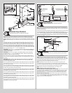
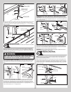
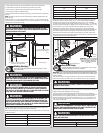
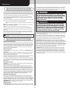
Ensure the Door is in a closed position and place vice clamps / c-clamps onto both vertical
tracks just above a track roller assembly. This is to prevent the garage door from rising while
winding torsion counterbalance spring(s).
WARNINGWARNING
FAILURE TO ENSURE DOOR IS IN A CLOSED POSITION AND TO PLACE
VICE CLAMP ONTO VERTICAL TRACK CAN ALLOW DOOR TO RAISE AND
CAUSE SEVERE OR FATAL INJURY.
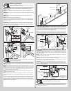
Vice clamps above third
track roller on both sides of
door
Bottom section
Vice clamps / C-Clamps attached to inner
and outer rail of vertical track
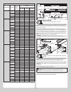
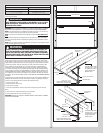
Winding Bars
(Steel Rods)
Size Of Winding Bar
(Inches)
Spring Diameter
Used On
1/2” dia. x 18”
5/8” dia. x 24”
2” and 2-5/8”
3-3/4”
C-Clamps
Typical sections
Winding Spring(s)
Tools Required: Step Ladder, Approved winding bars, 3/8” Wrench, Leather
gloves, Safety glasses
25
WARNINGWARNING
WINDING TORSION SPRING(S) IS AN EXTREMELY DANGEROUS PROCE-
DURE AND SHOULD BE PERFORMED ONLY BY A TRAINED DOOR SYSTEM
TECHNICIAN USING PROPER TOOLS AND INSTRUCTIONS.
WARNINGWARNING
USE ONLY SPECIFIED WINDING BARS, AS STATED IN STEP SECURING
DOOR FOR SPRING WINDING. DO NOT SUBSTITUTE WITH SCREWDRIV-
ERS, PIPE, ETC. OTHER TOOLS MAY FAIL OR RELEASE FROM THE SPRING
CONE AND CAUSE SERIOUS PERSONAL INJURY.
WARNINGWARNING
PRIOR TO WINDING OR MAKING ADJUSTMENTS TO THE SPRINGS, EN-
SURE YOU’RE WINDING IN THE PROPER DIRECTION AS STATED IN THE
INSTALLATION INSTRUCTIONS. OTHERWISE THE SPRING FITTINGS MAY
RELEASE FROM SPRING IF NOT WOUND IN THE PROPER DIRECTION AND
COULD RESULT IN SEVERE OR FATAL INJURY.
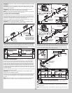
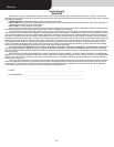
Position a ladder slightly to the side of the spring so that the winding cone is easily acces-
sible, and so your body is not directly in line with the winding bars.
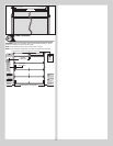
Check the label attached to the spring warning tag for the required number of complete turns
to balance your door.
Door Height Approximate Spring Turns
6’0” 6-7/8
6’3” 7-1/8
6’6” 7-1/4
6’8” 7-3/8
6’9” 7-1/2
7’0” 7-5/8
7’3” 7-7/8
7’6” 8
7’9” 8-1/4
8’0” 8-3/4
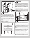
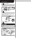
Alternately inserting the winding rods into the holes of the spring winding cone, rotate the
winding cone upward toward the ceiling, 1/4 turn at a time, until the required number of
complete turns for your door height is achieved. As the last 1/8 to 1/4 turn is achieved,
securely hold the winding rod and carefully stretch the torsion spring 1/8” - 1/4”. Next while
still securely holding the winding rod, tighten both set screws in the winding cone to 14-15 ft.
lbs. of torque (once set screws contact the torsion shaft, tighten screws one full turn).
Carefully remove winding rod from winding cone. Repeat for the opposite spring. While
holding the door down to prevent it from raising unexpectedly in the event the spring(s) were
over-wound, carefully remove the locking pliers from the torsion shaft and vertical tracks.
Adjustments to the number of turns stated may be necessary. If door rises off floor under
spring tension alone, reduce spring tension until door rests on the floor. If the door is hard to
rise or drifts down on its own, add spring tension.
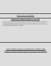
HIGH SPRING TENSION CAN CAUSE
SERIOUS INJURY OR DEATH.
DO NOT adjust, repair or remove springs or parts to
which springs are connected, such as steel brack-
ets, cables, wood blocks, fasteners or other parts of
the counterbalance system.
Adjustments or repairs must ONLY be made by a
trained door systems technician using proper tools
and instructions.
DO NOT remove, cover or paint over this tag. Prod-
uct user should inspect this tag periodically for
legibility and should order a replacement tag from
the door manufacturer, as needed.
©Copyright 2010 Overhead Door Corporation
102081 REV2 06/24/2010
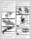
Torsion shaft
Winding
cone
Torsion
spring(s)
Approved
winding
rod
Set screws
IMPORTANT: CHECK THE WARNING
TAG(S) ATTACHED TO THE SPRING(S)
FOR THE REQUIRED NUMBER OF
COMPLETE TURNS, TO BALANCE
YOUR DOOR.
Warning
tag(s)
Approved winding rod
Torsion spring(s) should be wound in the direction the end coil points.
Spring
coils
Rear Back Hangs
Tools Required: Ratchet wrench, Socket: 1/2” 5/8”, Wrench: 1/2” 5/8”, (2) Vice
clamps, Tape measure, Level, Hammer, Step Ladder
26
IMPORTANT: HOLD THE DOOR DOWN TO PREVENT IT FROM RISING UNEXPECTEDLY IN THE
EVENT THE SPRING(S) WAS OVER-WOUND AND CAUTIOUSLY REMOVE VICE CLAMPS FROM
VERTICAL TRACKS.
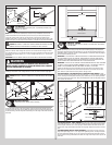
Raise the door until the top section and half of the next section are in the horizontal track
radius. Do not raise door any further since rear of horizontal tracks are not yet supported.
WARNINGWARNING
RAISING DOOR FURTHER CAN RESULT IN DOOR FALLING AND CAUSE
SEVERE OR FATAL INJURY.
Clamp a pair of vice clamps onto the vertical tracks just above the second track roller on one
side, and just below the second track roller on the other side. This will prevent the door from
raising or lowering while installing the rear back hangs.
Using the chart (Perforated Angle Gauge Weight Limitations) below, use the appropriate
perforated angle (may not be supplied), (2) 5/16” x 1-5/8” hex head lag screws and (3) 5/16”
bolts with nuts (may not be supplied), fabricate rear back hangs for the horizontal tracks.
Attach the horizontal tracks to the rear back hangs with 5/16” - 18 x 1” hex bolts and nuts
(may not be supplied). Horizontal tracks must be level and parallel with door within 3/4” to
7/8” maximum of door edge.
WARNINGWARNING
EXCEEDING THE RECOMMENDED LISTED DOOR WEIGHT LIMITATIONS OF
SPECIFIC GAUGE PERFORATED ANGLES MAY RESULT IN DOOR FALLING
WHEN RAISED, CAUSING SEVERE OR FATAL INJURY.
WARNINGWARNING
VERIFY PERFORATED BACK HANG ANGLE LOAD RATINGS WITH BACK
HANG ANGLE SUPPLIER.
Perforated Angle Gauge Weight Limitations:
Perforated Angle Gauge Door Weight
2” x 2” x 12 Gauge Door Weight Less Than 800 lbs.
15