


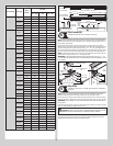


Perforated Angle Gauge Weight Limitations:
1-1/4” x 1-1/4” x 13 Gauge Door Weight Less Than 305 lbs.
1-1/4” x 1-1/4” x 15 Gauge Door Weight Less Than 220 lbs.
1-1/4” x 1-1/4” x 16 Gauge Door Weight Less Than 175 lbs.
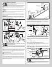
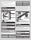
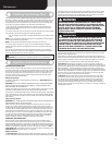
NOTE: If an opener is installed, position horizontal tracks one hole above level when securing
it to the rear back hangs.
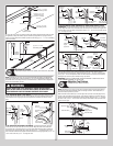
WARNINGWARNING
KEEP HORIZONTAL TRACKS PARALLEL AND WITHIN 3/4” TO 7/8” MAXI-
MUM OF DOOR EDGE, OTHERWISE DOOR COULD FALL, RESULTING IN
SEVERE OR FATAL INJURY.
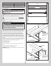
IMPORTANT: DO NOT SUPPORT THE WEIGHT OF THE DOOR ON ANY PART OF THE REAR
BACK HANGS THAT CANTILEVERS 4” OR MORE BEYOND A SOUND FRAMING MEMBER.
NOTE: If rear back hangs are to be installed over drywall, use (2) 5/16” x 2” hex head lag
screws and make sure lag screws engage into solid structural lumber.
NOTE: 26” angle must be attached to sound framing members and nails should not be
used.
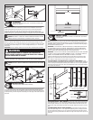
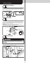
Now, permanently attach the weatherstrips on both door jambs and header. The weather-
strips were temporarily attached in Preparing the Opening, in the pre-installation section of
this manual.
NOTE: When permanently attaching the weatherstrips to the jambs, avoid pushing the weath-
erstrips too tightly against the face of door.
WARNINGWARNING
PRIOR TO WINDING OR MAKING ADJUSTMENTS TO THE SPRINGS, EN-
SURE YOU’RE WINDING IN THE PROPER DIRECTION AS STATED IN THE
INSTALLATION INSTRUCTIONS. OTHERWISE THE SPRING FITTINGS MAY
RELEASE FROM SPRING IF NOT WOUND IN THE PROPER DIRECTION AND
COULD RESULT IN SEVERE OR FATAL INJURY.
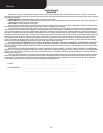
Now, lift door and check its balance. Adjustments to the required number of spring turns
stated may be necessary. If door rises off floor under spring tension alone, reduce spring
tension until door rests on the floor. If the door is hard to rise or drifts down on its own, add
spring tension. A poorly balanced door can cause garage door operator operation problems.
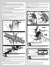
To adjust spring tension, fully close door. Apply vice grips to track above third track roller.
Insert a winding rod into the winding cone. On single spring doors, counterbalance lift
cable tension must be maintained by placing vice grips on torsion shaft before loosening
set screws in the winding cone. Push upward on the winding rod while carefully loosening
the set screws in the winding cone. BE PREPARED TO SUPPORT THE FULL FORCE OF THE
TORSION SPRING ONCE THE SET SCREWS ARE LOOSE. Carefully adjust spring tension 1/4
turn. Retighten both set screws in the winding cone and repeat for the other side. Recheck
door balance. DO NOT ADJUST MORE THAN 1/2 TURN FROM THE RECOMMENDED NUMBER
OF TURNS.
If the door still does not operate easily, lower the door into the closed position, UNWIND THE
SPRING(S) FULLY (Reference the insert “Removing The Old Door / Preparing The Opening”
section on torsion spring removal) and recheck the following the items:
1.) Check the door for level.
2.) Check the torsion shaft for level.
3.) Check the track spacing.
4.) Check the counterbalance cables for equal tension and proper wrap onto the cable
drums.
5.) Check the track for potential obstruction of the track rollers.
6.) Clamp locking pliers onto track and rewind springs.
IMPORTANT: IF DOOR STILL DOES NOT OPERATE PROPERLY, THEN CONTACT A TRAINED
DOOR SYSTEM TECHNICIAN.
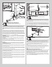
Vice clamp
Horizontal tracks
2nd Track roller
Vice clamp
5/16”-18 x 1-1/4”
Hex bolt must extend into the
track to serve as a roller stop
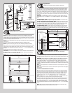
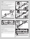
Perforated angle
Sound framing
members
Horizontal
track
(3) 5/16” Bolts and nuts
Perforated angle bolted
using (2) 5/16” x 1-5/8”
hex head lag screws to
ceiling member and
parallel to door
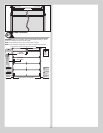
Perforated angle
Sound framing
members
Horizontal
track
(3) 5/16”
Bolts and nuts
Perforated angle bolted
using (2) 5/16” x 1-5/8”
hex head lag screws to
ceiling member and
parallel to door
5/16”-18 x 1-1/4”
Hex bolt must extend into the
track to serve as a roller stop
16