


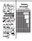
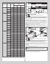
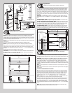

Strutting Schedule
Section Quantity Section Type
Solid or
Windows
Door Width
6’0” - 10’0” 12’0” 13’0” - 18’0”
4
Top
Solid N/A All - 2” Strut All - 2” Strut
Windows 2” Strut N/A N/A
Intermediate I
Solid N/A N/A N/A
Windows 2” Strut 2” Strut N/A
Lock Solid N/A N/A N/A
Bottom Solid N/A N/A All - 2” Strut
5
Top
Solid N/A All - 2” Strut All - 2” Strut
Windows 2” Strut N/A N/A
Intermediate II
Solid N/A N/A N/A
Windows 2” Strut 2” Strut N/A
Intermediate I
Solid N/A N/A All - 2” Strut
Windows 2” Strut 2” Strut N/A
Lock Solid N/A N/A N/A
Bottom Solid N/A N/A All - 2” Strut
6
Top
Solid N/A All - 2” Strut All - 2” Strut
Windows 2” Strut N/A N/A
Intermediate III
Solid N/A N/A All - 2” Strut
Windows 2” Strut 2” Strut N/A
Intermediate II
Solid N/A N/A N/A
Windows 2” Strut 2” Strut N/A
Intermediate I
Solid N/A N/A N/A
Windows 2” Strut 2” Strut N/A
Lock Solid N/A N/A All - 2” Strut
Bottom Solid N/A N/A All - 2” Strut
7
Top
Solid N/A All - 2” Strut All - 2” Strut
Windows 2” Strut N/A N/A
Intermediate IV
Solid N/A N/A All - 2” Strut
Windows 2” Strut 2” Strut N/A
Intermediate III
Solid N/A N/A N/A
Windows 2” Strut 2” Strut N/A
Intermediate II
Solid N/A N/A All - 2” Strut
Windows 2” Strut 2” Strut N/A
Intermediate I
Solid N/A N/A N/A
Windows 2” Strut 2” Strut N/A
Lock Solid N/A N/A All - 2” Strut
Bottom Solid N/A N/A All - 2” Strut
8
Top
Solid N/A All - 2” Strut All - 2” Strut
Windows 2” Strut N/A N/A
Intermediate V
Solid N/A N/A All - 2” Strut
Windows 2” Strut 2” Strut N/A
Intermediate IV
Solid N/A N/A N/A
Windows 2” Strut 2” Strut N/A
Intermediate III
Solid N/A N/A All - 2” Strut
Windows 2” Strut 2” Strut N/A
Intermediate II
Solid N/A N/A All - 2” Strut
Windows 2” Strut 2” Strut N/A
Intermediate I
Solid N/A N/A N/A
Windows 2” Strut 2” Strut N/A
Lock Solid N/A N/A All - 2” Strut
Bottom Solid N/A All - 2” Strut All - 2” Strut
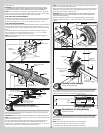
1/4”-14 x 7/8” Self drilling
screws
Typical
upper
hinge
leaf
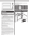
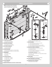
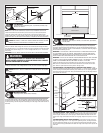
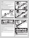
Strut installation
for other sections
Strut installation
for top section
Strut
Strut
Strut installation at
top of top section
Strut installation for other sections
Typical lower
hinge leaf
1/4”-14 x 7/8” Self drilling
screws
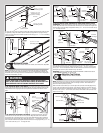
End hinges
Center hinge(s)
Top fixture
(If applicable)
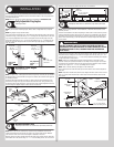
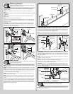
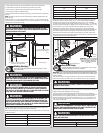
Top Fixtures (B)
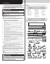
Tools Required: Power drill, 7/16” Socket driver, Saw horses
8
NOTE: Using the illustrations below and referring to Package Contents / Parts Breakdown, to
determine if you have Top Fixture Assemblies or not. If you have Top Fixture Bases and Top
Fixture Slides, skip this step.
Starting on the left hand side, align the top fixture base 3” down from the top section or
below strut and even with the edge of the top section. The slotted half of the top fixture base
should be facing upwards. Fasten to section using (4) 1/4” - 14 x 7/8” self drilling screws.
The top fixture slide will be tightened and adjusted later, in step, Adjusting Top Fixture. Insert
short stem track roller into top fixture slide. Repeat same process for other right hand side.
NOTE: If needed, ensure the top fixture slides are able to slide back and forth along the top
fixture bases. If needed, loosen the 1/4” - 20 flange hex nuts.
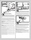
IMPORTANT: IF NO STRUT WAS INSTALLED ON THE TOP SECTION, PLACE (1) 1/4” - 14 X
7/8” SELF DRILLING SCREW INTO THE TOP PRE-PUNCHED HOLE IN EACH ENDSTILE OF THE
TOP SECTION.
(4) 1/4”-14 x 7/8”
Self drilling screws
Top fixture
base
(2) 1/4”-20 Flange hex
nuts
Top fixture
slide
Short stem track roller
End
cap
Top section
Top
section
End
cap
3”
(4) 1/4”-14 x 7/8”
Self drilling screws
Strut
(1) 1/4”-14 x 7/8”
Self drilling screw
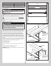
Step Plate
Tools Required: Power Drill, 7/16” Drill Bit, Phillips Screwdriver, Tape Measure,
Saw horses
9
NOTE: Refer to door section identification, located in the pre-installation section of this
manual to determine what size sections you need to use as your bottom section.
On the inside of the bottom section, locate the vertical center of the door. Center the inside
step plate vertically no higher than 8” from the bottom of the door to the top of the step plate.
IMPORTANT: DO NOT MOUNT THE STEP PLATE HIGHER THAN 8” FROM THE BOTTOM OF
THE SECTION.
Using the inside step plate’s second top most hole and bottom hole as a template, mark and
drill 7/16” diameter holes through the entire section.
CAUTION: BE CAREFUL TO KEEP DRILL STRAIGHT WHEN PRE-DRILLING. SECTION
DAMAGE CAN RESULT FROM FAILURE TO KEEPING THE DRILL STRAIGHT.
Insert the outside step plate into the holes through the front of the door, mounting the two
step plates back to back. Next, secure both step plates together using two No. 8 screws
through the inside step plate and into the outside step plate.
8