


Page 2
NOTE: See Outdoor Installation section regarding
roof overhang.
These clearances are the minimum acceptable.
Whenever possible, larger clearances should be provided to
assure adequate room for service operations. Note that gas
piping may be provided through either side of the unit. See
later section on gas piping.
Do not install the heater on carpeting or similar
material.
2C-3. Flooring - Typical Installation
The heater must not be installed on combustible
flooring without special measures to assure that the floor
temperatures will not be excessive.
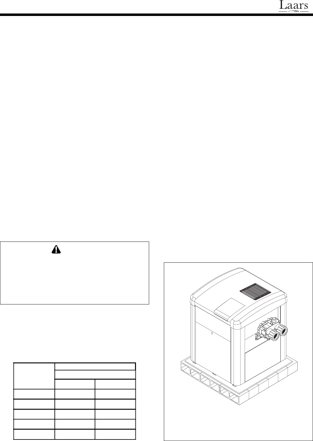
A special base for combustible floors may be
obtained from Waterpik Technologies. The part number
appears in the parts list at the back of this manual (see
Section 5)
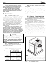
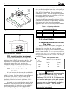
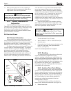
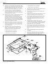
In the United States, the National Fuel Gas Code
allows a heater to be placed on a combustible surface when
there is a platform under the heater made of hollow
masonry no less than 4 inches (102millimeters [mm])
thick, covered with sheet metal at least 24 gauge thick and
extending beyond the full width and depth of the heater by
at least 6 inches (76.2mm) in all directions. The masonry
must be laid with ends unsealed, and joints matched to
provide free circulation of air from side to side through the
masonry (see Figure 1).
It is best to handle these preparations before the
heater is installed in its final location. Instructions are
provided in subsequent sections of this document.
Contact Waterpik Technologies regarding
installations at elevations above 3,000 feet (980 m). It is
necessary to make changes to the burner tray to assure
proper operation.
2C. Heater Location
2C-1. Installation Information
The LX and LT can be installed outdoors or indoors
as outlined in later sections. In either case location must
be selected with consideration of vent gas exhaust and in
the case of indoor installation, the location must have
suitable provisions for combustion and ventilation air.
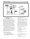
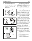
Avoid placing the heater in locations where it can
cause damage by water leakage. If this is not possible,
provide a suitable drain pan to catch and divert any
leakage. The pan must not block natural flow of air to or
around the heater.
When a heater or any system component is located
below the pool surface a leak can result in large scale
water loss or flooding. Waterpik Technologies cannot be
responsible for such water loss or flooding. Location of a
heater below or above the pool surface affects operation of
the heater pressure switch. See sections on water piping
and heater start-up for more information about this.
CAUTION
When pool equipment is located below the
pool surface, a leak from any component can
cause large scale water loss or flooding.
Waterpik Technologies cannot be responsible
for such water loss or flooding or resulting
damage.
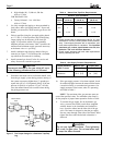
2C-2. Installation Clearances
Clearances between the heater and combustible
material must be per Table 1.
Figure 1. Non-Combustible Platform.
Notes:
1. Blocks must provide solid base and be braced so they
cannot slip out of place.
2. Air openings in blocks must be arranged to provide
unrestricted opening through entire width or length of
base.
Table 1. Minimum Heater Clearances from
Combustible Surfaces
Side of
Heater
A ll Ins ta lla tio ns
U.S. and Canada
inch (cm)
Blank 4 (10.2)
Rear 4 (10.2)
Piping 12 (30.5)
To p 3 9 (9 9 .0 )
Front 18 (45.7)