Page 18
SECTION 3.
Operating Instructions
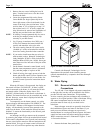
Lighting and shutdown instructions are posted inside
the heater.
Do not attempt repairs on the gas control or
appliance. Tampering is dangerous and voids
all warranties.
LP GAS: To avoid possible injury, fire and
explosion, read and follow these precautions
and all instructions on this appliance before
starting the heater. LP (propane) gas is
heavier than air and will remain at ground level
if there is a leak. Before lighting, sniff at
ground level. If you smell gas, follow these
rules:
1. DO NOT light matches. DO NOT turn
electric lights or switches on or off in
area. DO NOT use an electric fan to
remove the gas from area.
2. Shut off gas at LP tank.
3. Telephone gas company and fire
department for instructions. Give your
name, address and phone number.
If your LP tank runs out of fuel, turn off gas at the
appliance. After the tank is refilled, the appliance must be
restarted according to the instructions located on the inside
of the door.
3A. Start-Up Procedure
With any new pool or spa installation, run the filter
pump with the heater off long enough to completely clean
the water. This removes any installation residue from the
water. Clean the filter at the end of this operation before
starting the heater. Do not operate the heater unless the
pool is properly filled with water.
When raising the temperature of water in a cold
pool, remove all time clock settings. This lets the filter
system and heater operate continuously until the water
reaches the temperature setting on the thermostat. When
that happens, the heater will shut off automatically, but the
filter pump will keep running.
5. Start the heater by setting the control panel to either
"Pool" or "Spa". Allow the heater to operate for five
minutes or more. Note and record the thermometer
reading. Subtract pool water temperature from this
reading. This difference is the temperature rise. Refer
to Table 8. If your measured temperature rise is
within the range designated for your heater, skip
steps 6 through 8.
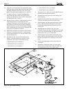
6. Locate the bypass adjustment screw on the right-hand
side of the header (see figure 20). Loosen the nut so
that the screw can be adjusted. A slight water leak
past the nut may be expected. Turn the screw
counterclockwise to decrease the temperature rise,
and clockwise to increase the temperature rise as
needed to achieve the ranges in Table 8. After the
adjustment, tighten the nut so that no leaks occur.
7. If the temperature rise is too low and cannot be raised
by means of the adjustment screw, the flow is in
excess of 125 GPM (7.9 l/s). An external bypass will
need to be installed, or if one already exists, open the
external bypass valve gradually until the temperature
range in Table 8 is achieved.
8. If it was necessary to adjust the external bypass as
outlined in step 6, scribe a line on the bypass shaft
and case to mark the correct adjustment position.
Wire or remove the valve handle to prevent
tampering.
Note that temperature rise is somewhat less when a
heater is derated for installation at elevations significantly
above sea level. For high elevation installations, reduce the
numbers in Table 8 by 3% per 1000 feet above sea level.
Table 8. Water Temperature Rise and Flow Rates
(Measured at Input/Output Header)
Minimum Maximum Minimum System
Model Temp Rise, Temp Rise, Flow
°F (C) °F (C) GPM (l/s)
250 24 (13) 28 (16) 30 (1.9)
400 36 (20) 40 (22) 30 (1.9)
In a system without external bypass, it may be
necessary to make changes. If temperature rise is too low,
a manual bypass must be installed. If temperature rise is
too high, there is inadequate flow, possibly requiring a
change to the piping system or a larger pump. Before
proceeding with either remedy, verify proper heater
operation. Low gas input results in low temperature rise
and vice-versa. A problem with the heater internal bypass
assembly also affects measured temperature rise.
WARNING
WARNING


