


Page 8
12. Before operating the heater, test the complete gas
supply system and all connections for leaks using a
soap solution. Do not use an open flame.
CAUTION
Some leak test solutions (including soap and
water) may cause corrosion or stress cracking.
Rinse the piping with water after testing.
2G-2. Special Precautions for
Propane Gas
Liquefied petroleum (LP) gas is heavier than air.
Therefore, do not install pool heaters using LP gas in pits
or locations where gas might collect. Locate heaters a safe
distance from LP gas storage and filling equipment.
Consult local codes and fire protection authorities about
specific installation restrictions.
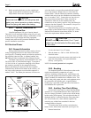
2H. Electrical Power
2H-1.General Information
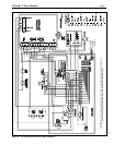
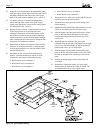
Wiring connections must be made exactly as shown
in the wiring diagram found on the inside of the heater
(see Figure 8 ). Grounding must be provided as required by
the prevailing electrical code. A separate bonding wire
MUST be provided as indicated in the following section
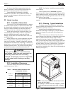
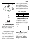
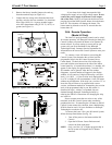
The heater comes factory-wired intended for use with
240 Volt, 60 Hz AC field electrical supply. To convert to
120 Volt, 60 Hz AC requires the changing of the fifteen-
pin connector assembly on the component raceway.
Remove the fifteen-pin connector from the receptacle
located directly below the fan intake on the raceway. All
the wires on the connector are red and the connector is
marked "240V". The fifteen-pin connector will have two
wires that lead to a two position terminal block located
next to the connector. Remove the two wires from the
terminal block. Take the fifteen-pin connector assembly
with the black wires from the installation and instructions
box. It is marked "120V". Connect the two long wires to
the two position terminal block. Either wire may be
connected to either tab on the terminal block, the
connections are not polarity sensitive. Plug the fifteen-pin
connector into the receptacle. The connector is keyed so it
will fit in only one orientation.
Electrical wiring must be in accordance with the
latest edition of the National Electric Code (NEC), ANSI/
National Fire Protection Association (NFPA) 70, unless
local code requirements indicate otherwise.
DO NOT connect power to the LX or LT pool
heater from the load side of a filter pump relay
or time clock.
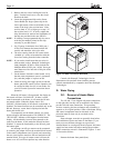
To wire the Laars LX or LT heater:
1. Wire the heater to a 120V or 240V /60 Hertz (Hz)
electrical source.
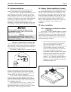
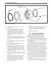
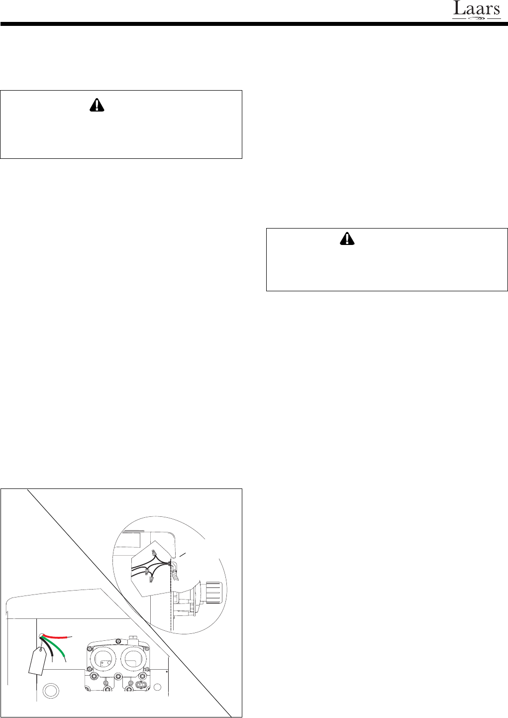
2. Connect the wires from the source to the leads on the
right side of the heater in the space behind the
raceway (see Figure 9).
NOTE: No external junction box is required.
2H-2. Bonding
The National Electrical Code and most other codes
require that all metallic components of a pool
structure, including reinforcing steel, metal fittings and
above ground equipment be bonded together with a solid
copper conductor not smaller than a number 8 wire. The
heater, along with pumps and other such equipment must
be connected to this bonding grid. A special labeled
bonding lug is provided on the right side of the heater to
accommodate this requirement.
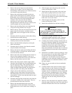
2H-3. Auxiliary Time Clock Wiring
If you install a time clock to control the filter pump
operation, it is recommended that the time clock have its
own low voltage (Firemans) switch to turn off the heater
before turning off the pump . The switch should shut off
the heater about 15 minutes before the filter pump shuts
off. This will allow for a more efficient operation by
removing any residual heat contained in the heat
exchanger back to the pool.
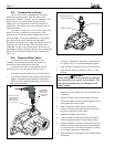
To install a time clock auxiliary switch into the
heater circuit, follow these instructions (see Figure 10):
1. Remove heater door.
CAUTION
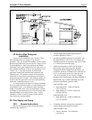
Figure 9. Field Wiring Connections.
WIRES
AS
SHIPPED
CONNECT
WIRES
INSIDE
HEATER
CONDUIT
ELBOW