


LX and LT Pool Heaters
Page 11
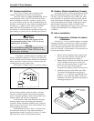
2. Remove the two hex head screws that hold the
raceway cover in place. They are located on the
bottom flange of the raceway cover. Slide the raceway
cover down to expose the raceway.
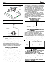
3. Remove the control panel assembly from the top
panel. Lift the control panel cover. Remove the two
philips head screws located at the front edge of the
bezel. Lift the front of the bezel up until the entire
assembly comes away from the top. Without
removing any wires, slip the control assembly
through the hole so that when the top is removed, the
control assembly will stay with the heater.
4. Remove the four philips head screws that fasten the
vent grill to the top. Remove the vent grill.
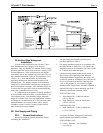
5. Remove the top. There are two hex head screws at the
upper corners of the raceway. And there are two
philips head screws at the upper corners of the rear
panel.
6. Disconnect the blower pressure switch rubber tubing
from the blower assembly housing.
7. Disconnect the two white wires from the vent switch
located just above the inlet/outlet header.
8. Remove the EMI shield (metal plate) covering the
motor on the blower.
9. Disconnect the five blower wires from the terminal
strip on the back of the raceway.
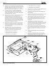
10. Remove the four hex head screws holding the blower
to the flue collector. Lift the blower and the exhaust
vent off of the flue collector.
11. Remove hex head screws holding the flue collector to
the top of the combustion chamber. There are 10
screws on a model 400 and 6 screws on a model 250.
Remove the flue collector and set it aside.
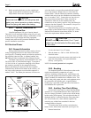
12. Remove the water pressure switch's copper siphon
loop tube from the header by first loosening the brass
nut at the pressure fitting. Then carefully pull the
tube out of the fitting. There should be about two
inches of tubing inside the header. Be careful not to
create any kinks in the tubing when handling it.
13. Clip the wire tie that bundles the wire harnesses
leading from the control panel. Disconnect the two
black temperature sensor wires from the back of the
control panel. Coil the wires and place them on top of
the heat exchanger.
14. Disconnect the high limit switch black wires from the
wire harness leading to the control panel. There are
quick disconnects at the end of the wires.
15. Remove the inlet/outlet header side cover plate
located under the inlet/outlet header. There are four
philips head screws, one in each corner, holding it in
place.
16. Slide the upper right side panel up and out of the
corner posts and place it aside.
17. Remove the left side cover panel, held to the lower
panel with two philips head screws at the corners.
18. Remove the flat return header side cover plate to
expose the return header by removing the four philips
head screws, one in each corner.
19. Slide the upper left side panel up and out of the
corner posts and place it aside.
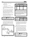
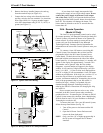
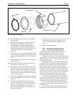
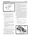
20. Remove the end baffles from the heat exchanger.
The heat exchanger is heavy.
It may be necessary to have help lifting the
heat exchanger to remove it and replace it on
the combustion chamber.
21. Lift the heat exchanger assembly off of the
combustion chamber and rotate it 180° so that the
inlet/outlet header is on the left side of the heater.
22. Carefully place the heat exchanger assembly back on
top of the combustion chamber. Be sure that the heat
exchanger is level and that the finned tubes fit
between the front and rear walls of the combustion
chamber. Be sure that the definned section of the
tubes, near the headers, fit into the slots cut in the top
of the insulation on the side walls of the combustion
chamber.
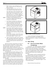
23. Reinstall the end baffles on the heat exchanger. Align
the cut out portion of one of the baffles with the cut
out section on the top of the front combustion
chamber wall. Set the baffle so that the flange fits
completely over the combustion chamber wall. Set the
other baffle on the rear combustion chamber wall in
the same manner.
Note: There is no cut out section on the rear combustion
chamber wall.
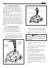
24. Carefully bend the water pressure switch's copper
siphon loop tube so that it reaches the inlet/outlet
header now on the left side of the heater. Do not
straighten out the coil behind the raceway and do not
kink the tubing. Straightening the coil or kinking
the tubing may result in poor heater operation. Insert
the end of the tube into the fitting on the header.
Tighten the nut onto the fitting one half turn past
hand tight.
25. Route the wires that attach to the high limit switches
along the copper siphon loop, back to the right side of
the heater. Reconnect the wires to the wire harness.
WARNING