


Page 14
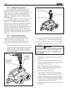
2I-3. Connections at Heater
The LX and LT have a standard two inch water
header and coupling design. With this feature, only
nominal two inch PVC or CPVC may be connected to the
heater. However, by installing the appropriate pipe
adapters and two short pieces of two inch plastic pipe
(supplied by the installer), any size existing pipe may be
fitted to the heater.
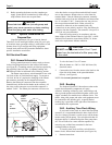
To connect a section of 2 PVC or CPVC pipe to the
heater, first slip a coupling nut onto the pipe. Then
prepare the end of the pipe with the proper PVC/CPVC
primer and glue. Follow the manufacturers instructions
provided with the primer and glue for preparation
procedures and curing times. Apply the slip-fit side of the
coupling to the end of the pipe. Allow the glue to cure
completely. Set the o-ring into the groove on the face of
the coupling. Slide the coupling nut up to the coupling and
tighten it to the threaded connection on the header (see
Figure 16).
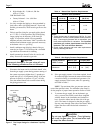
2I-4. Pressure Relief Valve
A pressure relief valve is mandatory in any
installation in which the water flow can be shut off
between the heater outlet and the pool/spa.
A pressure relief valve is not supplied with the
heater however, it may be required by local codes.
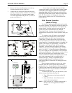
To install a pressure relief valve, do the following:
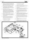
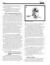
1. To protect the threads while drilling, screw the brass
adapter (included with the Waterpik Technologies
PRV kit) into the blind threaded hole on the top of
the inlet/outlet header.
2. Using the countersink in the center of the blind hole
as a guide, drill a 1/4 inch hole through the plastic.
3. Open the hole by reaming it with a 3/8 inch drill bit.
4. Open the hole again by reaming it with a 1/2 inch
drill bit.
Initially drilling a 1/2 inch hole without reaming
may cause the bit to "grab" on the plastic. This
may cause personal injury or damage to the
plastic header.
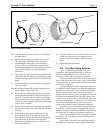
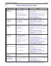
5. Remove the brass adapter and clean the cuttings out
of the hole.
6. Install the rubber washer at the bottom of the hole.
7. Thread the adapter into the hole and tighten so that it
seals against the rubber washer.
8. With a permanent marker, place a mark on the
adapter so that the mark faces the same direction as
the water connections on the header.
9. Remove the adapter from the hole.
10. Coat the threads of the pressure relief valve (PRV)
with an appropriate metal to metal thread sealant.
11. Install the adapter on the PRV and tighten using two
wrenches. Use the mark made earlier on the adapter
to orient the PRV to the desired direction in relation
to the water connections on the header.
12. Wrap the threads of the adapter with a suitable teflon
thread tape.
WARNING
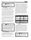
Figure 18. Pressure Relief Valve Installation.
RUBBER WASHER
BRASS ADAPTER
PRESSURE RELIEF VALVE
HAND TIGHTEN ONLY
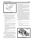
Figure 17. Drill Hole For Pressure Relief Valve
START WITH 1/4" BIT
THEN OPEN HOLE
WITH A 3/8" BIT
THEN OPEN HOLE
WITH A 1/2" BIT
TEMPORARILY
INSTALL BRASS
ADAPTER TO
PROTECT PLASTIC
THREADS